4: SPECIAL FUNCTIONS
4-16 USER’S MANUAL
Computer Link Function
A personal computer can be connected to one MICRO
3
base unit in a peer-to-peer configuration (1:1 communication) or to
a maximum of 32 MICRO
3
base units in a network configuration (1:N communication).
Using the optional software CUBIQ (FC9Y-LP1E314) on an IBM PC or compatible, user programs can be edited on the
computer and transferred between the computer and MICRO
3
. It is also possible to monitor from the computer the opera-
tion of the MICRO
3
system, current values of timers and counters, the data in data registers, and the statuses of inputs and
outputs. MICRO
3
can be started or stopped from the computer. Preset values for timers and counters, and data in data regis-
ters can also be changed. Ladder diagrams, mnemonic lists, FUN tables, and labels can be printed out from the computer
on a printer.
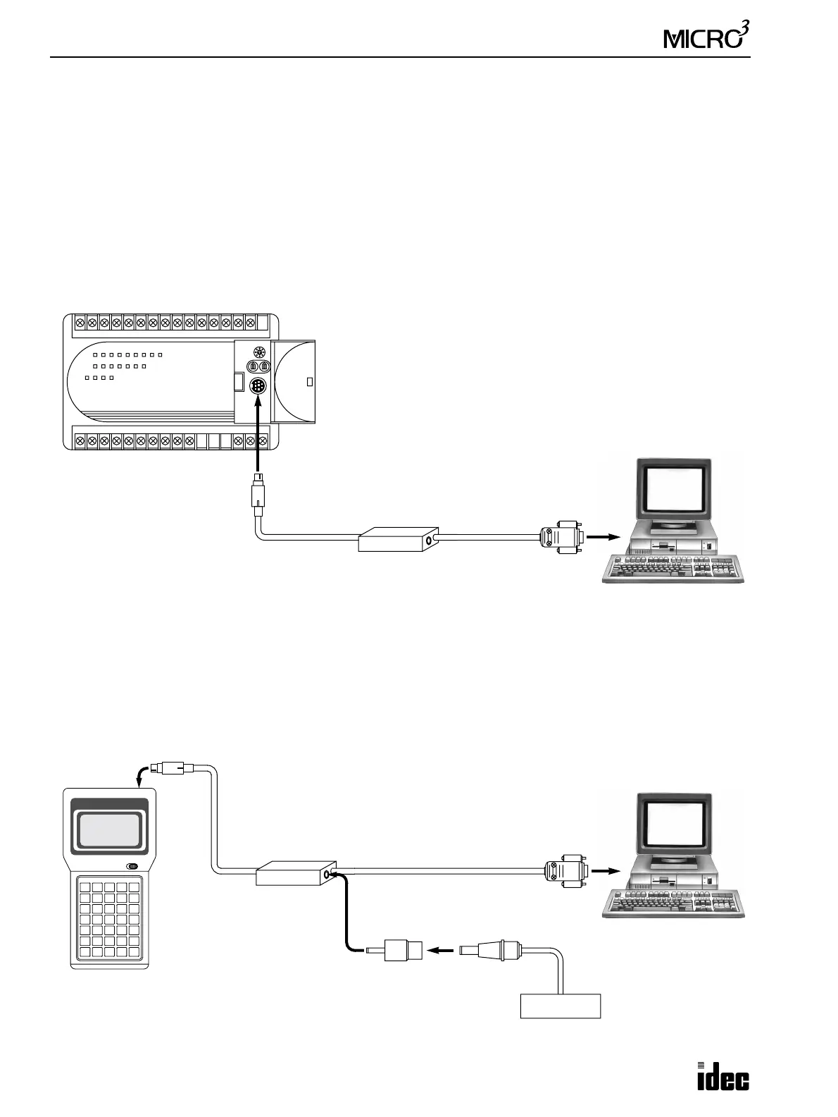
Computer Link 1:1 Communication
To set up a 1:1 computer link system, connect a computer to MICRO
3
using computer link cable FC2A-KC2.
Use FUN8 Loader Port Communication Mode Setting to make sure that the communication parameters for the MICRO
3
loader port are the same as the computer connected. For FUN8, see page 5-7.
Communication between the program loader and computer
The program loader can also be connected to an IBM PC or compatible using computer link cable FC2A-KC2 for commu-
nication. An AC adapter is required to power the program loader. Connect the computer link cable to the loader cable con-
nection port on the program loader. Plug the jack converter into the converter box on the computer link cable and plug the
AC adapter into the jack converter. For specifications of an applicable AC adapter, see page A-4.
Computer Link Cable
FC2A-KC2
2m (6.56 ft.) long
To Loader Port
D-sub 9-pin
Female Connector
To RS232C Port
◆ For the MICRO
3
C, see the MICRO
3
C User’s Manual. ◆
Computer Link Cable
FC2A-KC2
2m (6.56 ft.) long
Jack Converter FC2A-CJ1
(included with computer link cable)
To RS232C Port
AC Adapter
D-sub 9-pin
Female Connector