7: BASIC INSTRUCTIONS
USER’S MANUAL 7-21
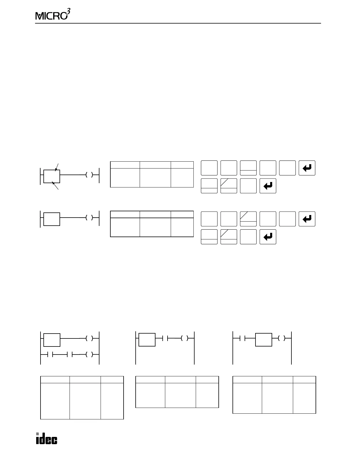
CC= and CC≥ (Counter Comparison)
The CC= instruction is an equivalent comparison instruction for counted values. This instruction will constantly compare
counted values to the value that has been programmed in. When the counter value equals the given value, the desired out-
put will be initiated.
The CC≥ instruction is an equal to or greater than comparison instruction for counted values. This instruction will con-
stantly compare counted values to the value that has been programmed in. When the counter value is equal to or greater
than the given value, the desired output will be initiated.
When a counter comparison instruction is programmed, two addresses are required. The circuit for a counter comparison
instruction must be programmed in the following order: the CC= or CC≥ instruction, a counter number 1 through 31, fol-
lowed by the preset value to compare from 0 to 9999.
The preset value can be designated using a decimal constant or a data register. When a data register is used, the data of the
data register becomes the preset value. If the data register designated as a counter comparison preset value holds a value
over 9999, a program execution error will result, then the error indicator, ERR1, is lit, and the special internal relay, M304,
turns on. Data registers D0 through D99 are available in the standard processing mode and D0 through D31 in the high-
speed processing mode.
• The CC= and CC≥ instructions can be used repeatedly for different preset values.
• The comparison instructions only compare the counted value. The status of the counter does not affect this function.
• The comparison instructions also serve as an implicit LOD instruction.
• The comparison instructions can be used with internal relays, which are AND’ed or OR’ed at a separate program
address.
• Like the LOD instruction, the comparison instructions can be followed by the AND and OR instructions.
• Another way to accomplish the above is to use comparison instructions which are then followed by the AND LOD or
OR LOD instructions.
Ladder Diagram (CC=)
Key Operation
LOD
10
0
1
BPS
RST
F
Q
0
OUT
16
Ladder Diagram (CC≥)
Key Operation
Prgm Adrs Instruction Data
0
2
CC≥
OUT
3
D15
Q1
Program List
Q1
>C3
D15
1
BPS
RST
F
Q
OUT
16
6
CC>=
3
BPP
5
CC=
1
BPS
Q0
=C2
10
Counter # to compare with
Preset value to compare
5
CC=
2
BRD
Prgm Adrs Instruction Data
0
2
CC=
OUT
2
10
Q0
Program List
OR
E
D
Ladder Diagram
M0
=C5
10
I0 M0
Q0
Prgm Adrs Instruction Data
0
2
3
4
5
CC=
OUT
LOD
AND
OUT
5
10
M0
I0
M0
Q0
Program List
Ladder Diagram
Q0
=C5
10
I0
Prgm Adrs Instruction Data
0
2
3
CC=
AND
OUT
5
10
I0
Q0
Program List
Prgm Adrs Instruction Data
0
1
3
4
LOD
CC=
AND LOD
OUT
I0
5
10
Q0
Program List
Ladder Diagram
Q0
=C5
10
I0