7: BASIC INSTRUCTIONS
7-20 USER’S MANUAL
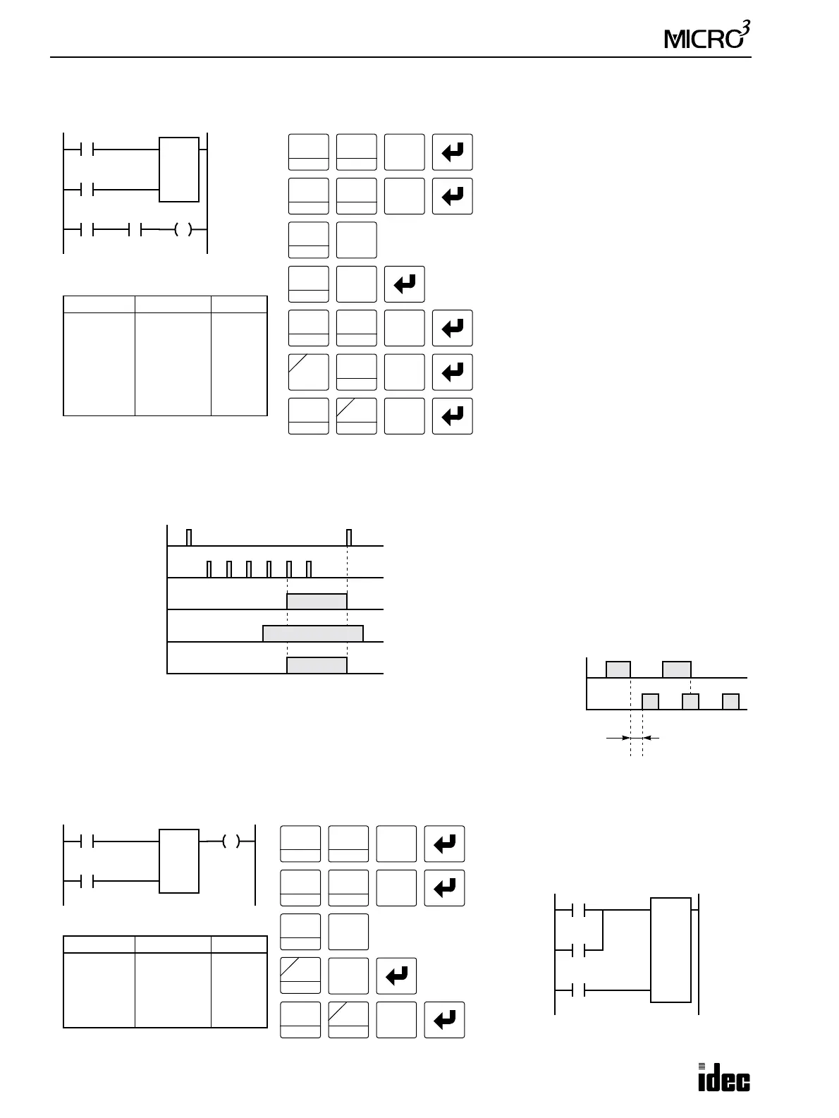
Adding (Up) Counters CNT2 through CNT31, continued
• The same counter or timer number cannot
be programmed more than once.
• While the reset input is off, the counter
counts the leading edges of pulse inputs
and compares them with the preset value.
• When the counted value reaches the preset
value, the counter turns output on. The
output stays on until the reset input is
turned on.
• When the reset input changes from off to
on, the counted value is reset.
• When the reset input is on, all pulse inputs
are ignored.
• The reset input must be turned off before
counting may begin.
• When power is off, the counter’s counted
value is held.
• Counter preset values can be changed
without transferring the entire program to
the MICRO
3
base unit (see page 3-14).
• When the preset value is changed during
counter operation, the change becomes
effective immediately.
• The reset input has priority over the pulse
input. One scan after the reset input has
changed from on to off, the counter starts
counting the pulse inputs as they change
from off to on.
• When MICRO
3
is turned off, counter cur-
rent values are maintained. When resetting
the counter current values is required at
start up, include initialize pulse special
internal relay M301 in an OR circuit with
the reset input.
I1
I0
Ladder Diagram (CNT2 to 31)
Key Operation
LOD
10
SET
I
OUT
16
RST
F
Q
Prgm Adrs Instruction Data
0
1
2
4
5
6
LOD
LOD
CNT
LOD
AND
OUT
I0
I1
2
5
I2
C2
Q0
Program List
C2
5
Q0
1
BPS
0
I2
Reset
Pulse
LOD
10
SET
I
CNT
C
LOD
10
5
CC=
0
Reset Input I0
ON
OFF
Pulse Input I1
ON
OFF
CNT2
ON
OFF
Timing Chart
Output Q0
ON
OFF
1
Input I2
• • •
C2
2
BRD
LOD
10
SET
I
2
BRD
AND
D
CNT
C
2
BRD
2345
ON
OFF
The preset value 0 through 9999 can be designated using a data register
D0 through D99 in the standard processing mode or D0 through D31 in
the high-speed processing mode, then the data of the data register
becomes the preset value. Directly after the CNT instruction with two
required addresses, the OUT (output) instruction can be keyed.
Prgm Adrs Instruction Data
0
1
2
4
LOD
LOD
CNT
OUT
I0
I1
2
D5
Q0
Program List
I1
I0
Ladder Diagram
C2
D5
Q0
Reset
Pulse
Key Operation
LOD
10
SET
I
OUT
16
RST
F
Q
1
BPS
0
LOD
10
SET
I
CNT
C
0
2
BRD
5
CC=
OR
E
D
Note: To enter a decimal con-
stant as a preset value, press the
LOD/10 key followed by the
preset value.
Reset
ON
OFF
Pulse
ON
OFF
More than one scan
time is required.
ValidInvalid
M301
I0
C2
10
I1
Preset
Pulse