18: TROUBLESHOOTING
18-6 USER’S MANUAL
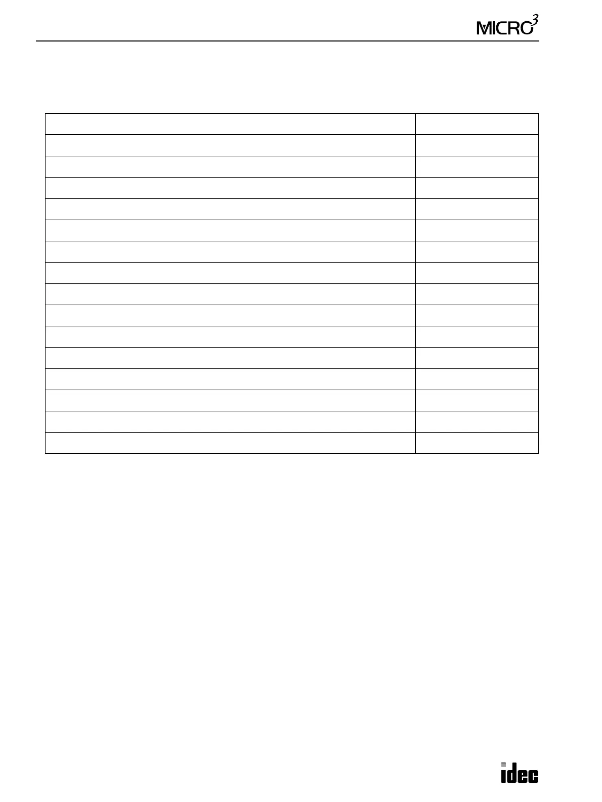
Troubleshooting Diagrams
When one of the following problems is encountered, see the troubleshooting diagrams on the following pages.
When using MICRO
3
C, also see the MICRO
3
C User’s Manual for troubles particular to the MICRO
3
C.
Problem Troubleshooting Diagram
The POW (power) indicator does not go on. Diagram 1
The RUN indicator does not go on. Diagram 2
Error indicator ERR1 is on. Diagram 3
Error indicator ERR2 is on. Diagram 4
Inputs do not operate normally. Diagram 5
Outputs do not operate normally. Diagram 6
Communication between the program loader and the MICRO
3
base unit is not possible. Diagram 7
Stop and reset operation cannot be performed. Diagram 8
Normal voltage does not appear on sensor power terminals. Diagram 9
Expansion link or data link is impossible. Diagram 10
Output pulses are not generated at output Q0 when using the PULS or PWM instruction. Diagram 11
High-speed counter does not work correctly. Diagram 12
The catch input function cannot receive short pulses. Diagram 13
The calendar/clock does not operate correctly. Diagram 14
Transfer to and from the memory card is impossible. Diagram 15