16: P
ULSE
, A/D C
ONVERSION
I
NSTRUCTIONS
U
SER
’
S
M
ANUAL
16-3
92 PWM (Pulse Width Modulation)
Key Operation
Valid Operands (Standard Processing)
In the high-speed processing mode, data registers for this instruction are limited to D0 through D31.
The pulse cycle period (MODE selection) cannot be changed during operation. To change the duty ratio during operation,
use a data register as source operand S1, and change the value of the data register. See page 3-16. If the value of the data
register designated as S1 is between 0 and 4, the pulse width coefficient is designated as 5.
When a data register is designated as S1, make sure the value of the data register does not exceed 249. If the value of the data
register designated as S1 exceeds 249 during operation, a user program execution error will occur, error indicator ERR1 on
the
MICRO
3
base unit is lit, and special internal relay M304 is turned on. Correct the program and transfer corrected program
to the base unit. When a data register is designated as S1, the data is read as the user program is scanned. When changing the
value of the data register designated as S1, change the value slowly in comparison to the output frequency.
When output Q0 is monitored on the program loader while the PWM instruction is executed, Q0 remains on, and the out-
put indicator also remains on. When input to the PWM instruction is turned off while the pulse output is on, the output is
turned off after a complete pulse is generated.
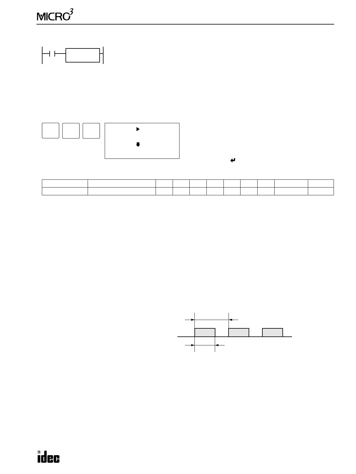
Output Pulse Width Ratio
Select MODE1 through MODE4 to determine the pulse cycle period. (Do not choose MODE5 and MODE6.)
The output pulse width ratio is determined by the following equation:
Variable Range of Pulse Width Ratio
When S1 is a data register: 2.4% through 100% in 0.4% increments
When S1 is a constant: 0.4% through 100% in 0.4% increments
To turn the pulse output off, turn the input to the PWM instruction off.
Operand Function I Q M T C R D Constant Repeat
S1 (Source 1) Pulse width coefficient ——————0-99 0-249 —
MODE Pulse Cycle Period
MODE1 51.2 msec
MODE2 25.6 msec
MODE3 3.2 msec
MODE4 1.6 msec
When input is on, output Q0 generates a pulse output. The period of the pulse output is
selected from 51.2, 25.6, 3.2, or 1.6 msec. The output pulse width ratio is determined by
source operand S1 according to the equation shown below.
When input is off, output Q0 remains off.
Note: Either the PULS or PWM instruction can be used only once in a user program.
Note: When the PWM instruction used in the protect source output type MICRO
3
, the output
protection function does not work on output Q0.
PWM
MODE1
S1
****
ADV
1 S1
PWM (*MODE1)
(Q0)
9
JMP/E
2
BRD
Enter operand S1 using the LOD/10 key for a decimal con-
stant, or designate a data register.
Select MODE1 through MODE4 using the REP key.
Do not choose MODE5 and MODE6.
To exit, press the key.
Period (51.2, 25.6, 3.2, or 1.6 msec)
Pulse Width = Period × Pulse Width Ratio
Pulse
Width
Ratio
Pulse
Width
Coefficient
S1 1+
250
---------------------------------------------------------------------------=
Pulse
Width Period
Pulse
Width
Coefficient
S1 1+
250
---------------------------------------------------------------------------
×
[msec]=