16: P
ULSE
, A/D C
ONVERSION
I
NSTRUCTIONS
16-4 U
SER
’
S
M
ANUAL
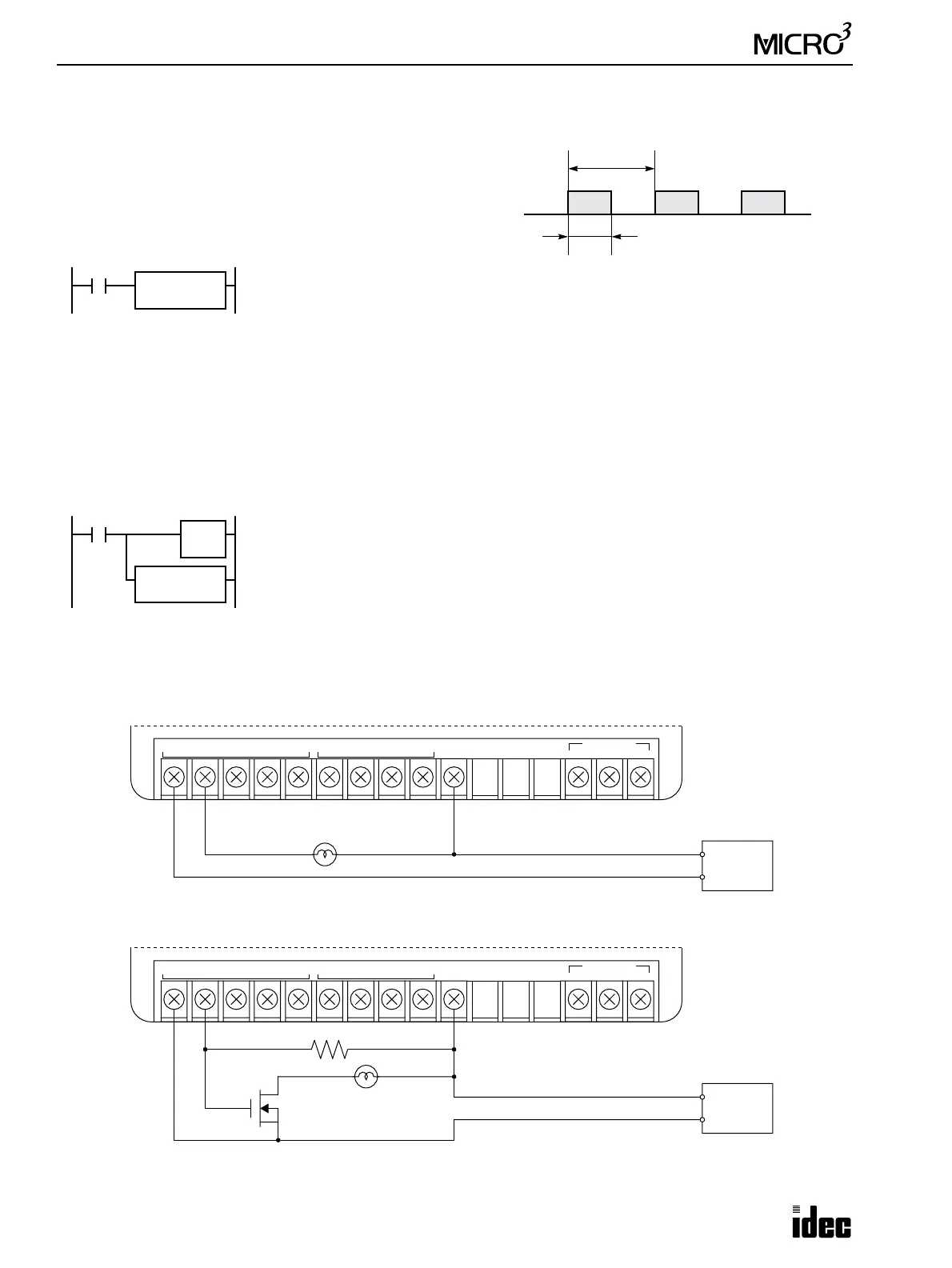
Example: PWM
When MODE1 (pulse cycle period 51.2 msec) is selected and 99 is set to S1, the output pulse waveform is as follows.
Example: Illumination Control Using PWM Instruction
This example demonstrates a program to control incandescent lamp illumination using the PWM instruction. Analog
potentiometer 0 is used to change the illumination intensity.
Operands
Q0 Pulse output
D20 Pulse width coefficient
MODE1 Pulse cycle period 51.2 msec
Output Wiring Diagram
When input I1 is on, output Q0 generates a pulse output shown above.
I1
S1
99
PWM
MODE1
Pulse
Width Period
Pulse
Width
Coefficient
S1 1+
250
---------------------------------------------------------------------------
×
=
51.2
msec
99 1+
250
---------------
×
=
20.48
msec=
51.2 msec
20.48 msec
M317
PWM
MODE1
S1
D20
ANR0
D20
M317 is the in-operation output special internal relay which remains on while the program is
executed.
The ANR0 (analog read 0) instruction sets the value of analog potentiometer 0 to data regis-
ter D20.
The PWM instruction is executed to generate output pulses. The pulse width ratio is deter-
mined by the value of data register D20. Output Q0 sends out the output pulses.
OUT
COM0(–)
0123
OUT
COM1(–)
456
DATA LINK
ASGB
+V
+
–
External
Power
24V DC
Incandescent Lamp
OUT
COM0(–)
0123
OUT
COM1(–)
456
DATA LINK
ASGB
+V
+
–
External
Power
24V DC
Incandescent Lamp
Note: Provide protection against a rush current depending on the load.
Transistor
Sink
Output
Transistor
Sink
Output
FET
• When using an incandescent lamp of 0.5A or less
• When using an incandescent lamp of 0.5A or more