1: GENERAL INFORMATION
1-24 USER’S MANUAL
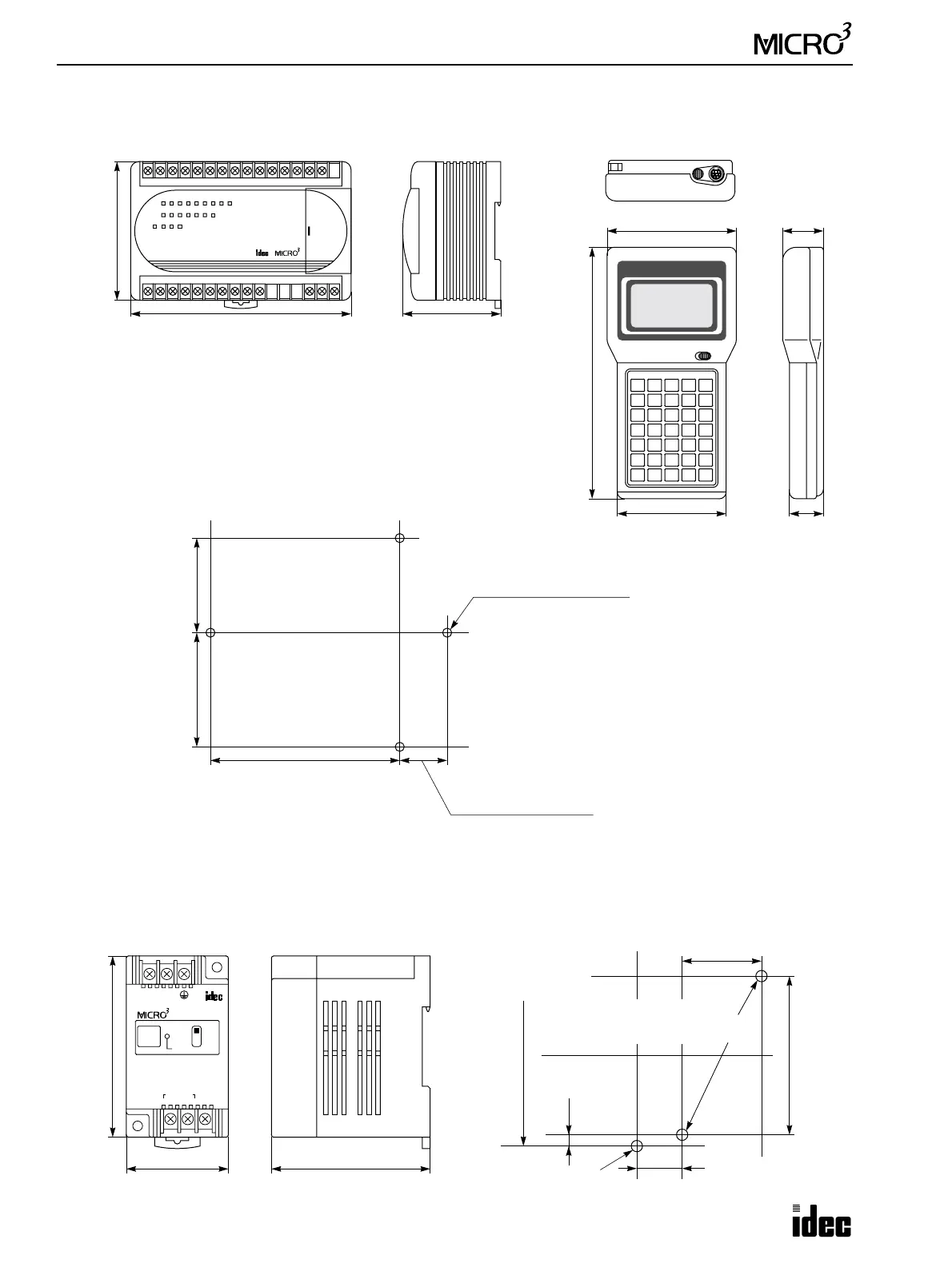
Dimensions
85 mm (3.346")
10-I/O Type: 105 mm (4.134")
16-I/O Type: 135 mm (5.315")
24-I/O Type: 165 mm (6.496")
AC Input Type: 165 mm (6.496")
60 mm (2.362")
95 mm (3.740")
30 mm
(1.181")
185 mm (7.283")
80 mm (3.150")
25 mm
(0.984")
10-I/O Type: 86 mm (3.386")
16-I/O Type: 116 mm (4.567")
24-I/O Type: 146 mm (5.748")
AC Input Type: 146 mm (5.748")
M4 tapped holes or
ø4.5 (0.177" dia.) drilled holes
77 mm
Minimum center to center
Minimum
29 mm (1.142")
(3.031")
center to center
58 mm (2.283")
Mounting Hole Layout for MICRO
3
Base Units
MICRO
3
Base Unit Program Loader
+–
24V DC
A/D UNIT
INPUT
4-20mA
POWER
SINK
SCE
+–
ANALOG WIRE TO
IN 0
INPUT OUTPUT
20 mm (0.787") minimum
70 mm (2.756")
35 mm (1.378")
3.5 mm
77 mm (3.031")
For mounting MICRO
3
M4 tapped holes or
ø4.5 (0.177") drilled holes
for mounting converter unit
(0.138")
A/D and D/A Converter Units Mounting Hole Layout
For A/D and D/A Converter Units
80 mm (3.150")
45 mm (1.772") 70 mm (2.756")