17: HIGH-SPEED COUNTER INSTRUCTIONS
USER’S MANUAL 17-3
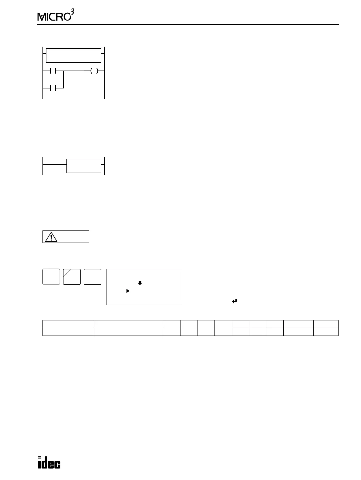
Example: HSC0
A2 HSC1 (Multi-stage Comparison)
The high-speed counter current value is reset to 0 when MICRO
3
is powered up. The high-speed counter holds the current
value while MICRO
3
is stopped and restarts counting input pulses starting with the existing current value. Include the hard
reset or soft reset in the user program, if necessary.
Note: Only one of HSC0 through HSC3 and A/D instructions can be used only once in a user program.
Key Operation
Valid Operands (Standard Processing)
In the high-speed processing mode, data registers for this instruction are limited to D0 through D31.
Allocation Numbers
The HSC1 instruction uses the following input and internal relay numbers:
Pulse input: Input I0
Hard reset input: Input I1
Soft reset special internal relay: Internal relay M315 (When M315 is on, the current value is reset to 0.)
Hard Reset Selection
Input I1 can be used to reset the current value of high-speed counter HSC1.
LOW: Resets the current value when input I1 is turned off. HSC1 is enabled while I1 is on.
HIGH: Resets the current value when input I1 is turned on. HSC1 is enabled while I1 is off.
*–––: Disables hard reset. (Input I1 can be used as an ordinary input.)
Operand Function I Q M T C R D Constant Repeat
S1 (Source 1) Multi-stage preset data ——————0-99 — —
HSC0
HIGH
I10
M301
S1 D1
Q01000
M315
I0: Pulse input
I1: Hard reset input (HSC0 is reset when I1 is on because the hard reset is set to HIGH.)
I10: Soft reset input to turn on soft reset special internal relay M315
M301 is the initialize pulse special internal relay used to turn soft reset special internal relay
M315 on at start up.
While hard reset input I1 is off, the HSC0 instruction counts input pulses to input I0. When
the HSC0 current value reaches 1000, output Q0 is turned on.
When hard reset input I1 or soft reset input I10 is turned on, the HSC0 current value is reset
to 0.
For monitoring high-speed counter preset and current values, see page 3-15.
Multi-stage high-speed counter HSC1 counts input pulses to input I0 and compares the cur-
rent value with multiple preset values. When the current value reaches the first preset value,
the first comparison output is turned on. When the second preset value is reached, the first
comparison output is turned off, the second comparison output is turned on, and so forth.
S1
****
HSC1
LOW
Caution
When a slave station performs communication at 19,200 bps through the loader port in the data link
system, multi-stage comparison instruction HSC1 cannot be used at the slave station.
ADV
0 (I0)
HSC1
S1
(*---)
Enter operand S1.
To select hard reset mode from LOW, HIGH, or unused,
press the REP key.
To exit, press the key.
NOT
A
2
BRD