8: ADVANCED INSTRUCTIONS
USER’S MANUAL 8-5
Using Input or Output as Source or Destination Operand
When an input or output is designated as a source or destination operand of an advanced instruction, 16 points starting
with the designated number are used. Depending on the MICRO
3
base unit used alone or in the expansion link system,
available input terminals are limited and special care is needed. In the standard processing mode, inputs I0 through I35 and
outputs Q0 through Q31 are available. In the high-speed processing mode, available I/O numbers are limited to I0 through
I15 and Q0 through Q11. Only these I/O numbers can be used for advanced instructions although the internal RAM has an
I/O area of I0 through I37 and Q0 through Q37 for processing user programs.
Input Source in the Move Instruction
Expansion
Link Station
Input No.
10-I/O Base Units
(6 input points)
16-I/O Base Units
(9 input points)
24-I/O Base Units
(14 input points)
Base
Station
I0 to I5 Input terminals available
Input terminals available
Input terminals available
I6 and I7
Always off (0)
I10
I11 to I15
Always off (0)
I16 and I17 Always off (0)
Expansion
Station
I20 to I25 Input terminals available
Input terminals available
Input terminals available
I26 and I27
Always off (0)
I30
I31 to I35
Always off (0)
I36 and I37 Always off (0)
Expansion
Link Station
Output No.
10-I/O Base Units
(4 output points)
16-I/O Base Units
(7 output points)
24-I/O Base Units
(10 output points)
Base
Station
Q0 to Q3 Output terminals available
Output terminals available
Output terminals available
Q4 to Q6
Impossible to output
Q7
Impossible to outputQ10 and Q11
Q12 to Q17 Impossible to output
Expansion
Station
Q20 to Q23 Output terminals available
Output terminals available
Output terminals available
Q24 to Q26
Impossible to output
Q27
Impossible to outputQ30 and Q31
Q32 to Q37 Impossible to output
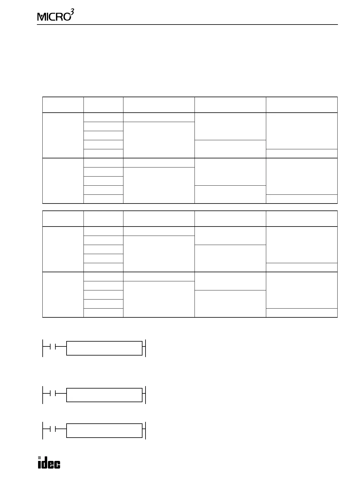
M317
MOV REP
**
S1
I0
D1
D0
M317 is the in-operation special internal relay which remains on during
operation.
The MOV (move) instruction sets data of 16 inputs I0 through I17 to data
register D0. When using a 10-I/O MICRO
3
base unit, input terminals for I6
through I17 are not available, and these upper bits are always set to 0.
The MOV (move) instruction sets data of 16 inputs I10 through I27 to data
register D10. When using two 16-I/O MICRO
3
base units in the expansion
link system, input terminals for I11 through I17 are not available, and these
intermediate bits are always set to 0.
The MOV (move) instruction sets data of 16 inputs starting with I30 to data
register D20. When using two 24-I/O MICRO
3
base units in the expansion
link system, input terminals for I36 through I47 are not available, and these
upper bits are always set to 0.
M317
MOV REP
**
S1
I10
D1
D10
M317
MOV REP
**
S1
I30
D1
D20