8: ADVANCED INSTRUCTIONS
8-6 USER’S MANUAL
Using Input or Output as Source or Destination Operand, continued
Output Destination in the Move Instruction
Discontinuity of Operand Areas
Each operand area is discrete and does not continue, for example, from input to output or from output to internal relay. In
addition, special internal relays M290 through M317 are in a separate area from internal relays M0 through M287.
Advanced instructions execute operation only on the available operands in the valid area. If invalid operands are desig-
nated, a user program syntax error occurs when transferring the user program to the MICRO
3
base unit.
0 NOP (No Operation)
Key Operation
Details of all other advanced instructions are described in following chapters.
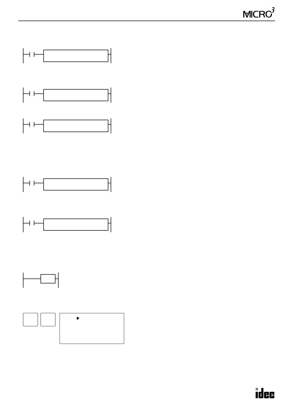
M317
MOV REP
**
S1
D0
D1
Q0
M317 is the in-operation special internal relay which remains on during
operation.
The MOV (move) instruction sets data of data register D0 to 16 outputs Q0
through Q17. When using a 10-I/O MICRO
3
base unit, output terminals for
Q4 through Q17 are not available, and these bits cannot be taken out.
The MOV (move) instruction sets data of D10 to 16 outputs Q10 through
Q27. When using two 16-I/O
MICRO
3
base units in the expansion link sys-
tem, output terminals for Q10 through Q17 and Q27 are not available, and
these bits cannot be taken out.
The MOV (move) instruction sets data of D20 to 16 outputs starting with
Q30. When using two 24-I/O MICRO
3
base units in the expansion link sys-
tem, output terminals for Q32 through Q47 are not available, and these bits
cannot be taken out.
M317
MOV REP
**
S1
D10
D1
Q10
M317
MOV REP
**
S1
D20
D1
Q30
M317
MOV REP
**
S1
M280
D1
D0
Since the internal relay ends at M287, the MOV (move) instruction sets only
8 internal relays M280 through M287 to data register D0. Upper 8 bits of
D0 are set to 0.
M317
MOV REP
2
S1
D0
D1 R
Q20
The MOV (move) instruction sets data of data register D0 to 16 outputs Q20
through Q37 in the first repeat cycle. The destination of the second cycle is
the next 16 outputs Q40 through Q57, which are invalid, resulting in a user
program syntax error, and error indicator ERR1 is lit.
For details of repeat operations, see the following chapters.
No operation is executed by the NOP instruction.
The NOP instruction may serve as a place holder. Another use would be to add a delay to the
MICRO
3
scan time, in order to simulate communication with a machine or application, for debugging pur-
poses.
NOP
ADV
No operands can be programmed for the NOP instruction.
0 NOP
1 END
5 END
6 END
0