13: BIT SHIFT / ROTATE INSTRUCTIONS
13-2 USER’S MANUAL
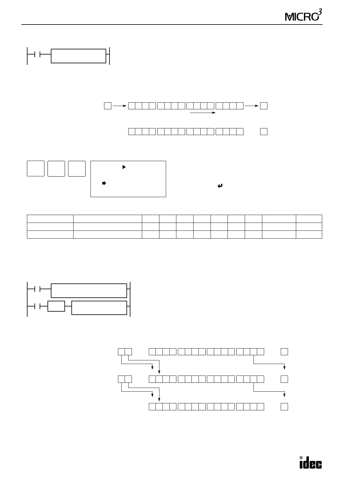
52 SFTR (Shift Right)
Key Operation
Valid Operands (Standard Processing)
In the high-speed processing mode, data registers for this instruction are limited to D0 through D31.
Since the bit shift instructions are executed in each scan while input is on, a pulse input from an SOTU or SOTD instruc-
tion should be used as required.
Example: SFTR
Operand Function I Q M T C R D Constant Repeat
S1 (Source 1) Data for bit shift ——————0-99 — —
bit Quantity of bits to shift ——————— 1-15 —
SFTR S1
****
bit
**
S1 → CY
When input is on, 16-bit data of the data register designated by source operand S1 is
shifted to the right by the quantity of bits designated by operand bit. The result is set
to the data register, and the last bit status shifted out is set to a carry (special internal
relay M303). Zeros are set to the MSB.
0Before shift: 1 0 1010 1 0 1 1 1101 0 0
MSB LSB
S1
After shift:
MSB LSB
S1
When bits to shift = 1
CY
M303
0
CY
M303
1 0 1010 1 0 1 1 1101 00
Shift to the right
ADV
2 S1
SFTR
( ) : 1bit
5
CC=
2
BRD
Enter operand S1 and the quantity of bits to shift.
Repeat cannot be designated for bit shift instructions.
To exit, press the key.
M301
SFTR
REP
**
M301 is the initialize pulse special internal relay.
When MICRO
3
starts operation, the MOV (move) instruction sets 29 to data
register D20.
Each time input I1 is turned on, 16-bit data of data register D20 is shifted to
the right by 2 bits as designated by operand bit. The last bit status shifted out
is set to a carry (special internal relay M303). Zeros are set to the MSB’s.
0Before shift: D20 = 29 0 0 0000 0 0 0 0 0110 1 1
CY
M303
MSB LSB
D20
0After first shift: D20 = 7 10 0000 0 0 0 0 1000 0 1
CY
M303
MSB LSB
D20
Bits to shift = 2
SOTU
I1
MOV S1
29
D1
D20
S1
D20
bit
2
0
10 0000 0 0 0 0 0000 0 0After second shift: D20 = 1
CY
M303
MSB LSB
D20
1
0
0