7: BASIC INSTRUCTIONS
7-28 USER’S MANUAL
MCS and MCR (Master Control Set and Reset)
The MCS (master control set) instruction is usually used in combination with the MCR (master control reset) instruction.
The MCS instruction can also be used with the END instruction, instead of the MCR instruction.
When the input preceding the MCS instruction is off, the MCS is executed so that all inputs to the portion between the
MCS and the MCR are forced off. When the input preceding the MCS instruction is on, the MCS is not executed so that
the program following it is executed according to the actual input statuses.
When the input condition to the MCS instruction is off and the MCS is executed, other instructions between the MCS and
MCR are executed as follows:
Input conditions cannot be set for the MCR instruction.
More than one MCS instruction can be set by one MCR instruction.
Corresponding MCS/MCR instructions cannot be nested within another pair of corresponding MCS/MCR instructions.
Instruction Status
SOTU Rising edges (ON pulses) are not detected.
SOTD Falling edges (OFF pulses) are not detected.
OUT All are turned off.
OUTN All are turned on.
SET and RST All are held in current status.
TIM, TMH, and TMS
Current values are reset to zero.
Timeout statuses are turned off.
CNT
Current values are held.
Pulse inputs are turned off.
Countout statuses are turned off.
SFR
Shift register bit statuses are held.
Pulse inputs are turned off.
The output from the last bit is turned off.
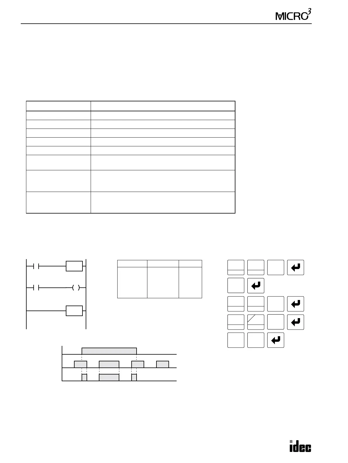
Ladder Diagram
Key Operation
I0
LOD
10
SET
I
0
RST
F
Q
Prgm Adrs Instruction Data
0
1
2
3
4
LOD
MCS
LOD
OUT
MCR
I0
I1
Q0
Program List
I1
1
BPS
Input I0
ON
OFF
Input I1
ON
OFF
Output Q0
ON
OFF
Timing Chart
LOD
10
SET
I
MCS
8
MCS/R
MCR
Q0
0
8
MCS/R
8
MCS/R
When input I0 is off, MCS is executed so that the subsequent
input is forced off.
When input I0 is on, MCS is not executed so that the following
program is executed according to the actual input statuses.
Note: Pressing the MCS/R key on
the program loader programs the
MCS or MCR instruction alter-
nately.
OUT
16