7: BASIC INSTRUCTIONS
USER’S MANUAL 7-29
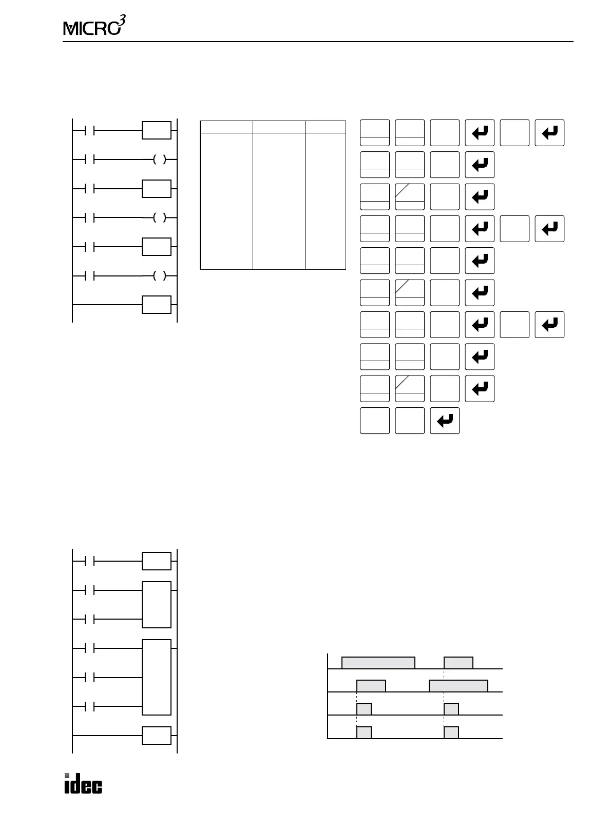
MCS and MCR (Master Control Set and Reset), continued
Multiple Usage of MCS instructions
Counter and Shift Register in Master Control Circuit
Ladder Diagram
Key Operation
I1
LOD
10
Prgm Adrs Instruction Data
0
1
2
3
4
5
6
7
8
9
10
11
12
LOD
MCS
LOD
OUT
LOD
MCS
LOD
OUT
LOD
MCS
LOD
OUT
MCR
I1
I2
Q0
I3
I4
Q1
I5
I6
Q2
Program List
OUT
16
RST
F
Q
0
2
BRD
Q0
I2
I3
I4
I5
I6
MCS
MCR
MCS
MCS
Q1
Q2
SET
I
1
BPS
8
MCS/R
LOD
10
SET
I
8
MCS/R
LOD
10
OUT
16
RST
F
Q
2
BRD
SET
I
1
BPS
8
MCS/R
LOD
10
SET
I
6
CC>=
3
BPP
5
CC=
4
LOD
10
OUT
16
RST
F
Q
SET
I
8
MCS/R
LOD
10
SET
I
8
MCS/R
This master control circuit will give priority to I1, I3, and I5, in that
order.
When input I1 is off, the first MCS is executed so that subsequent
inputs I2 through I6 are forced off.
When input I1 is on, the first MCS is not executed so that the fol-
lowing program is executed according to the actual input statuses of
I2 through I6.
When I1 is on and I3 is off, the second MCS is executed so that
subsequent inputs I4 through I6 are forced off.
When both I1 and I3 are on, the first and second MCS’s are not executed so that the following program is executed
according to the actual input statuses of I4 through I6.
Ladder Diagram
I1
MCS
MCR
I2
I3
R0
4
Reset
Pulse
I4
Data
I2
I3
C2
10
Reset
Pulse
Input I1
ON
OFF
Counter Pulse Input
ON
OFF
Shift Register Pulse Input
ON
OFF
Timing Chart
Input I2
ON
OFF
When input I1 is on, the MCS is not executed so that the counter and shift register are
executed according to actual statuses of subsequent inputs I2 through I4.
When input I1 is off, the MCS is executed so that subsequent inputs I2 through I4 are
forced off.
When input I1 is turned on while input I2 is on, the counter and shift register pulse
inputs are turned on as shown below.