9: MOVE INSTRUCTIONS
USER’S MANUAL 9-3
12 MOVN (Move Not)
Key Operation
Valid Operands (Standard Processing)
In the high-speed processing mode, operands for advanced instructions are limited. See page 6-1.
When T (timer) or C (counter) is used as S1, the timer/counter current value is read out. When T (timer) or C (counter) is
used as D1, the data is written in as a preset value which can be 0 through 9999.
When a bit operand such as input, output, internal relay, or shift register is used as the source or destination, 16 points are
used. When repeat is designated for a bit operand, the quantity of operand bits increases in 16-point increments.
Examples: MOVN
Operand Function I Q M T C R D Constant Repeat
S1 (Source 1) Operand to move 0-35 0-31 0-317 0-31 0-31 0-63 0-99 0-65535 1-31
D1 (Destination 1) Operand to move to — 0-31 0-287 0-31 0-31 0-63 0-99 — 1-31
MOVN S1(R)
*****
REP
**
D1(R)
****
S1 NOT → D1
When input is on, 16-bit word data from operand designated by S1 is
inverted bit by bit and moved to operand designated by D1.
ADV
1
BPS
1 S1
MOV
N D1:
Enter operands S1 and D1.
When repeat is required, press the REP key for the operand
to repeat, and enter the number of repeat cycles.
To exit, press the key.
2
BRD
I0
MOVN REP
**
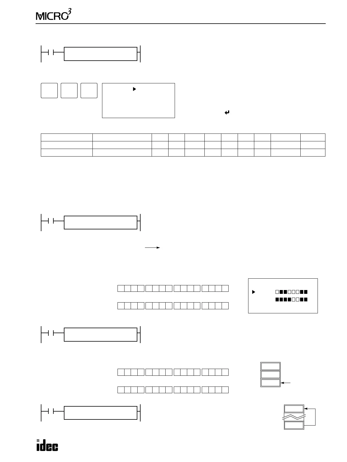
M10 NOT → M50
When input I0 is on, the 16 internal relays starting with M10 designated by
source operand S1 are inverted bit by bit and moved to 16 internal relays
starting with M50 designated by destination operand D1.
M10 through M17, M20 through M27 NOT
S1
M10
D1
M50
M50 through M57, M60 through M67
The ON/OFF statuses of the 16 internal relays M10 through M17 and M20 through M27 are inverted and moved to 16 inter-
nal relays M50 through M57 and M60 through M67. When M50 and M60 are monitored on the program loader, the data is
displayed as shown on the right below. M50 is the LSB (least significant bit), and M67 is the MSB (most significant bit).
Before inversion (M27-M10): 0 1 0010 0 0 0 1 0010 1 1
MSB LSB
S1
After inversion (M67-M50):
1 0 1101 1 1 1 0 1101 0 0
MSB LSB
D1
MON
M 50
M 60
I1
MOVN REP
**
810 NOT → D2
When input I1 is on, decimal constant 810 designated by source operand S1
is converted into 16-bit binary data, and the ON/OFF statuses of the 16 bits
are inverted and moved to data register D2 designated by destination oper-
and D1.
D1
D0
64725
D2
810
S1
810
D1
D2
Before inversion (810): 0 0 1000 0 1 0 1 1000 1 0
MSB LSB
S1
After inversion (64725): 1 1 0111 1 0 1 0 0111 0 1
MSB LSB
D1
I2
MOVN REP
**
D10 NOT → D2
When input I2 is on, the data in data register D30
designated by S1 is inverted bit by bit and moved
to data register D20 designated by D1.
64605
D20
930
D30
S1
D30
D1
D20