4: SPECIAL FUNCTIONS
4-6 USER’S MANUAL
Expansion Link Function
I/O points can be expanded by connecting another MICRO
3
base unit using a shielded 2-core twisted cable. Only one unit
can be added to expand I/O points from 10, 16, or 20 points up to 48 points. The expansion link function cannot be used
with the data link function or in the high-speed processing mode.
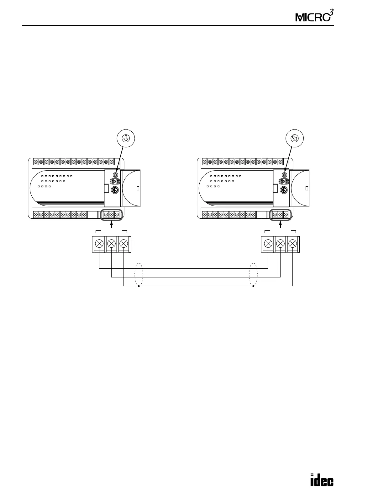
Expansion Link System Setup
To set up an expansion link system, connect the data link terminals of both units using an expansion cable FC2A-KE1
(250mm or 9.84" long) or a shielded twisted pair cable with a minimum core wire diameter of 0.9 mm (0.035") as shown
below. The cable for the expansion link system can be extended up to 200 meters (656 feet).
Set the function selector switch to 0 at the base station and to 7 at the expansion station.
Operating Procedure for Expansion Link System
Power up both MICRO
3
base units at the same time or power up the expansion station first. If the expansion station is pow-
ered up later than the base station, the base station does not recognize the expansion station. To recognize the expansion
station in this case, execute FUN27 Link Formatting Sequence at the base station (see page 5-11) or turn on M307 Link
Communication Initialize Flag at the master station (see page 6-3).
The scan time is extended by approximately 10 msec in the expansion link system.
If any communication error occurs in the expansion link system, communication error codes can be set to control data reg-
ister D94. For details of link communication error codes, see page 18-5. To enable the control data register, use FUN10
Control Data Register Setting. See page 5-8. If a communication error occurs, the data is resent three times. If the error
still exists after three attempts, the error code is set to data register D94.
The program loader can be connected to the base station only. If the program loader is connected to the expansion station,
an error will result and error message “Expansion Unit” is displayed on the program loader.
The RUN indicator on the expansion station remains off whether the base station is running or stopped.
7
3
4
5
62
1
0
7
3
4
5
62
1
0
MICRO
3
Base Station MICRO
3
Expansion Station
Set the function
selector switch to 0.
Set the function
selector switch to 7.
DATA LINK
ASGB
DATA LINK
ASGB
Expansion Cable FC2A-KE1, 250 mm (9.84") long
200 meters (656 feet) long maximum
Core wire diameter 0.9 mm (0.035") minimum