4: SPECIAL FUNCTIONS
USER’S MANUAL 4-7
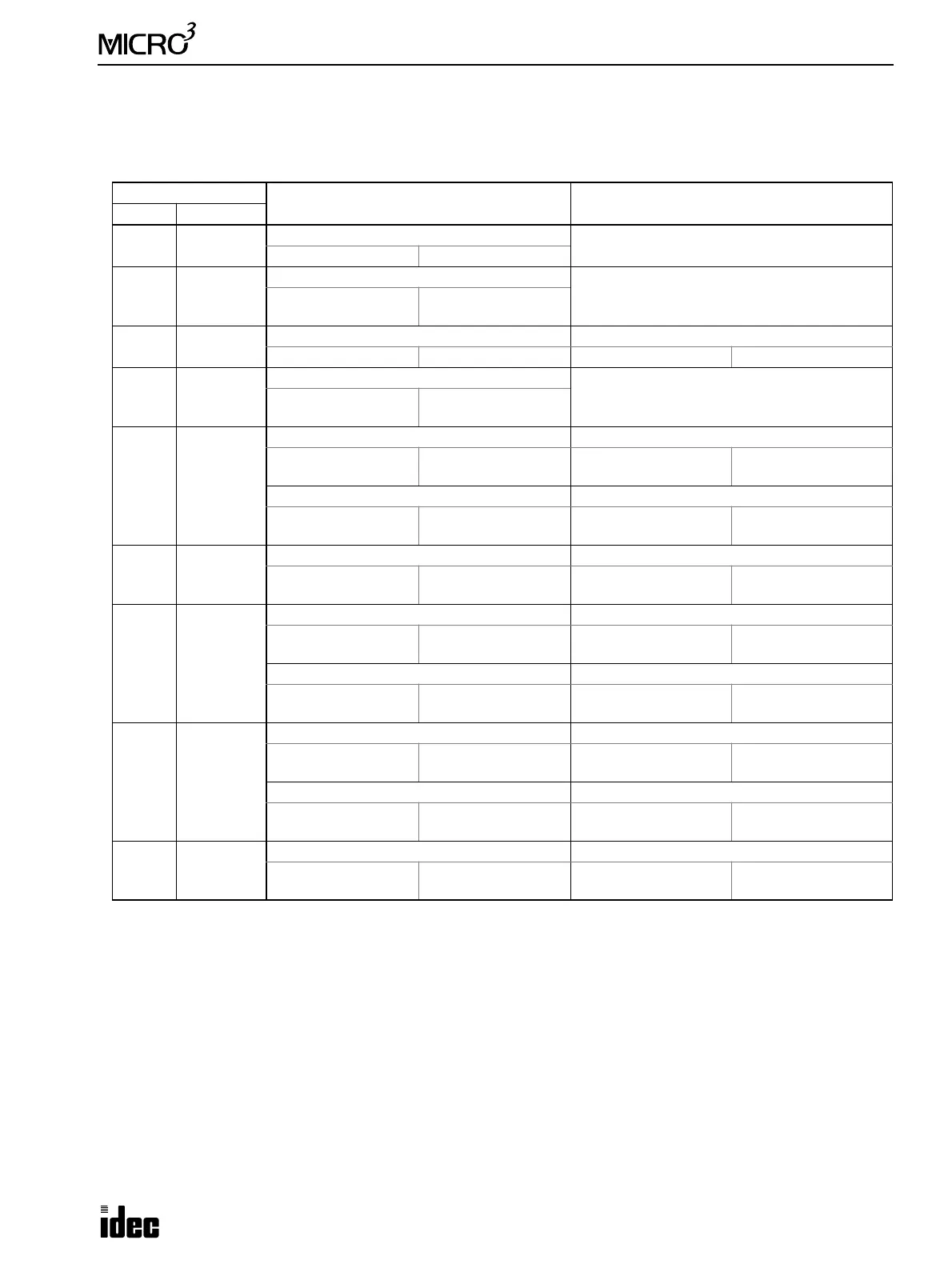
I/O Allocation Numbers for Expansion Link System
Input and output allocation numbers do not continue from the base station to the expansion station. At the expansion sta-
tion, inputs start at I20 and outputs start at Q20. Inputs and outputs are allocated depending on the MICRO
3
base units used
in the expansion link system as shown below:
Other allocation numbers for the expansion system are the same as the basic system. For other allocation numbers, see
page 6-1.
I/O Points
MICRO
3
Base Station
I/O Allocation Numbers
MICRO
3
Expansion Station
I/O Allocation Numbers
Total IN/OUT
10 6/4
10-I/O Type
———
I0 - I5 Q0 - Q3
16 9/7
16-I/O Type or AC input Type
———
I0 - I7
I10
Q0 - Q6
20 12/8
10-I/O Type 10-I/O Type
I0 - I5 Q0 - Q3 I20 - I25 Q20 - Q23
24 14/10
24-I/O Type
———
I0 - I7
I10 - I15
Q0 - Q7
Q10 - Q11
26 15/11
10-I/O Type 16-I/O Type or AC input Type
I0 - I5 Q0 - Q3
I20 - I27
I30
Q20 - Q26
16-I/O Type or AC input Type 10-I/O Type
I0 - I7
I10
Q0 - Q6 I20 - I25 Q20 - Q23
32 18/14
16-I/O Type or AC input Type 16-I/O Type or AC input Type
I0 - I7
I10
Q0 - Q6
I20 - I27
I30
Q20 - Q26
34 20/14
10-I/O Type 24-I/O Type
I0 - I5 Q0 - Q3
I20 - I27
I30 - I35
Q20 - Q27
Q30 - Q31
24-I/O Type 10-I/O Type
I0 - I7
I10 - I15
Q0 - Q7
Q10 - Q11
I20 - I25 Q20 - Q23
40 23/17
16-I/O Type or AC input Type 24-I/O Type
I0 - I7
I10
Q0 - Q6
I20 - I27
I30 - I35
Q20 - Q27
Q30 - Q31
24-I/O Type 16-I/O Type or AC input Type
I0 - I7
I10 - I15
Q0 - Q7
Q10 - Q11
I20 - I27
I30
Q20 - Q26
48 28/20
24-I/O Type 24-I/O Type
I0 - I7
I10 - I15
Q0 - Q7
Q10 - Q11
I20 - I27
I30 - I35
Q20 - Q27
Q30 - Q31