1: GENERAL INFORMATION
USER’S MANUAL 1-27
Wiring
Power Supply Wiring
Use a stranded wire of 1.25 mm
2
cross section (AWG16) for power supply wiring. Make the power supply wiring as short
as possible and run the wiring as far away as possible from motor lines.
To prevent electrical shocks or malfunctioning due to noise, connect the FG terminal to the ground using a grounding wire
of 2 mm
2
cross section (AWG14) minimum (grounding resistance 100Ω maximum). Do not connect the grounding wire in
common with the grounding wire of motor equipment.
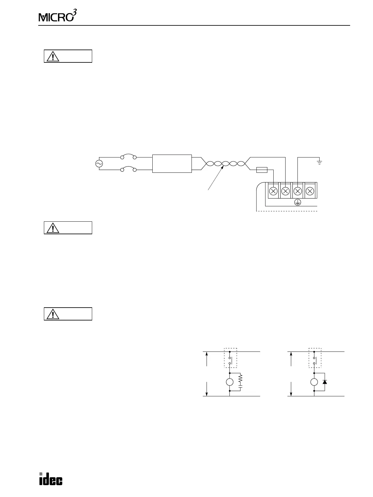
When using MICRO
3
on AC power, noise can be greatly reduced by connecting a 1:1 transformer as shown below:
Input Wiring
Use wire between 0.75 and 1.25 mm
2
cross section (AWG18 and AWG16) for input wiring. Separate the input wiring from
the output line, power line, and motor line. For input wiring diagrams, see pages 1-21 and 1-22.
Output Wiring
Use wire between 0.75 and 1.25 mm
2
cross section
(AWG18 and AWG16) for output wiring.
When driving loads which generate noise, such as elec-
tromagnetic contactors and solenoid valves, use a surge
absorber for AC power or a diode for DC power.
For output wiring diagrams, see page 1-23.
Data Link Wiring
For wiring the data link terminals in the expansion link or data link system, use a two-core twisted pair shielded cable with
a minimum core wire diameter of 0.9 mm. Separate the data link wiring from the output line, power line, and motor line.
Caution
• Use wires of a proper size to meet voltage and current requirements. Tighten M3 screws for power
and I/O terminals to a proper tightening torque of 0.3 to 0.5 N-m.
• Do not disassemble, repair, or modify the
MICRO
3
.
100-240V AC
LN
100-240V AC
Ground
50/60Hz, 30 VA
Transformer
1:1
Circuit Breaker
Stranded Wire 1.25mm
2
AWG16 minimum
3A Fuse
Caution
• Do not connect to the ground directly from the MICRO
3
. Connect a protective ground to the equip-
ment containing MICRO
3
using an M4 or larger screw. This is required when exporting equipment
containing MICRO
3
to Europe.
• Use an EU-approved circuit breaker. This is required when exporting equipment containing
MICRO
3
to Europe.
• If relays or transistors in the MICRO
3
output circuit fail, outputs may remain on or off. For output
signals which may cause heavy accidents, provide a monitor circuit outside of the MICRO
3
.
• Use an IEC127-approved fuse on the output circuit. This is required when exporting equipment
containing MICRO
3
to Europe.
Caution
MICRO
3
DC
L
Output
Power
Source
MICRO
3
AC
L
Output
Power
Source
(+)
(–)
Surge
Absorber
Diode