16: P
ULSE
, A/D C
ONVERSION
I
NSTRUCTIONS
U
SER
’
S
M
ANUAL
16-5
93 A/D (Analog/Digital Conversion)
Note:
Either the A/D or HSC (high-speed counter) instruction can be used only once in a user program. The A/D converter
unit can be connected to input I0 of
MICRO
3
at the base station only, not at the expansion station.
Key Operation
Valid Operands (Standard Processing)
In the high-speed processing mode, data registers for this instruction are limited to D0 through D31.
Digital Data Range
Depending on the resolution of A/D conversion, the digital data stored in the data register is limited to the range shown
below:
If the input to the A/D converter unit exceeds the input range, an overflow occurs and 250 is set.
Resolution
When the user program is cleared from the program loader memory, the resolution for the A/D instruction is set to the
default value of 8 bits.
Although pressing the REP key on the program loader toggles the resolution between 8 bits and 12 bits, select the resolu-
tion of 8 bits for programming the
MICRO
3
used with the A/D converter unit (FC2A-AD1, -AD2, -AD3, -AD4, or -AD5).
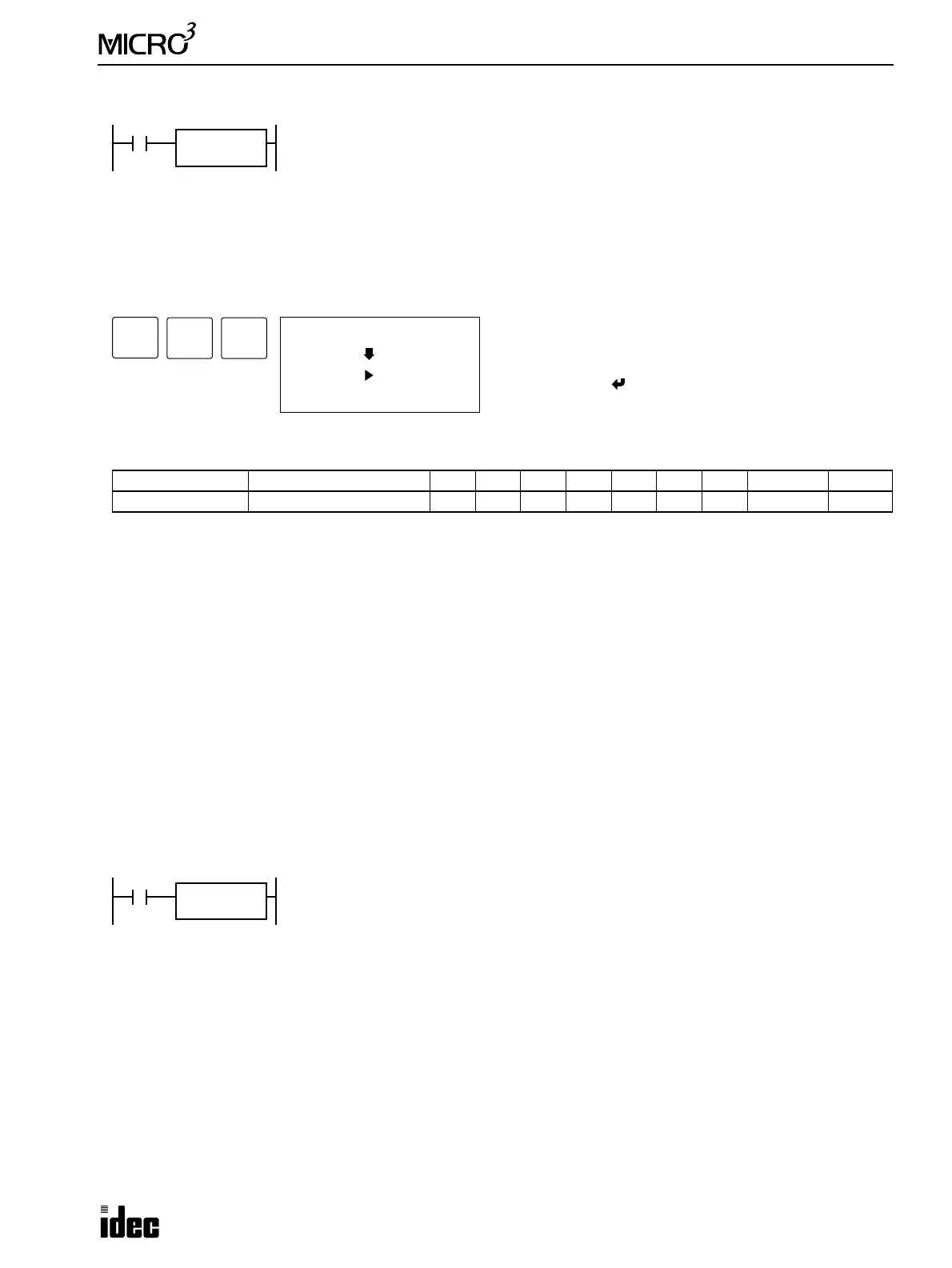
Example: A/D
Operand Function I Q M T C R D Constant Repeat
D1 (Destination 1) Destination to store data ——————0-99 — —
Resolution Digital Data Range
8 bits 0 through 249, or 250
When input is on, the analog data from the A/D converter unit (FC2A-AD1, -AD2, -AD3,
-AD4, or -AD5) connected to input I0 is converted to a digital value and set to a data register
designated by destination operand D1.
Resolution of the A/D conversion is 8 bits. Conversion time is 125 msec.
A/D
08
D1
****
ADV
1 (I0)
A/D
D1
(* 8bit)
Enter operand D1.
Select the resolution of 8 bits using the REP key.
To exit, press the key.
9
JMP/E
3
BPP
I2
D1
D20
When input I2 is on, the analog data from the A/D converter unit is converted to a digital
value with an 8-bit resolution and set to data register D20.
A/D
08