4: SPECIAL FUNCTIONS
4-8 USER’S MANUAL
Data Link Function
MICRO
3
features the data link function to set up a distributed control system. A maximum of six slave stations can be con-
nected to the master station. Data of inputs, outputs, internal relays, timers, counters, shift registers, and data registers are
communicated between the master and slave stations. The master station has five data registers assigned for each slave sta-
tion. Each slave station has five data registers assigned for communication with the master station. When data is set in a
data register at the master station assigned for data link communication, the data is sent to the corresponding data register
at a slave station. When data is set in a data register at the slave station assigned for data link communication, the data is
sent to the corresponding data register at the master station. Therefore, any particular program is not required for sending
or receiving data in the data link communication system.
The data link function cannot be used with the expansion link function or in the high-speed processing mode. When a
slave station performs communication at 19,200 bps through the loader port, multi-stage comparison instruction HSC1
cannot be used at the slave station.
MICRO
3
can also be connected to FA-3S series serial interface module PF3S-SIF4 mounted with high-performance CPU
module PF3S-CP12 or PF3S-CP13. Since two serial interface modules can be mounted with one CPU, a maximum of 12
MICRO
3
base units can be connected to the FA-3S master station in the data link system. For details, see page 4-13.
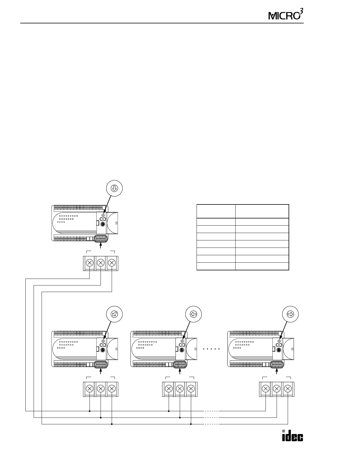
Data Link System Setup
To set up a data link system, connect the data link terminals of every unit using a shielded twisted pair cable as shown
below. The total length of the cable for the data link system can be extended up to 200 meters (656 feet).
7
3
4
5
62
1
0
Master Station
Set the function
selector switch to 0.
DATA LINK
ASGB
7
3
4
5
62
1
0
Slave Station 1
Set the function
selector switch to 1.
DATA LINK
ASGB
7
3
4
5
62
1
0
Slave Station 2
Set the function
selector switch to 2.
DATA LINK
ASGB
7
3
4
5
62
1
0
Slave Station 6
Set the function
selector switch to 6.
DATA LINK
ASGB
Shielded twisted pair cable
200 meters (656 feet) maximum
Core wire diameter 0.9 mm (0.035") minimum
Set the function selector switch to a unique
number at the master and slave stations. Slave
station numbers need not be consecutive.
Station
Function Selector
Switch
Master 0
Slave 1 1
Slave 2 2
Slave 3 3
Slave 4 4
Slave 5 5
Slave 6 6