USER’S MANUAL 4-1
4: SPECIAL FUNCTIONS
Introduction
MICRO
3
features special functions such as the high-speed processing mode, catch input function, input filter function,
pulse output function, high-speed counter function, expansion and data link functions, external analog timer function, and
analog I/O functions. This chapter describes these special functions.
High-speed Processing Mode
MICRO
3
can execute the user program in the standard processing mode and the high-speed processing mode. The high-
speed processing mode is ideal for using MICRO
3
as a sensor controller or executing a user program when high-speed pro-
cessing is required. The processing mode can be selected using FUN5 on the program loader. See page 5-5.
Using the high-speed processing mode, program capacity and available operand numbers are limited as shown below.
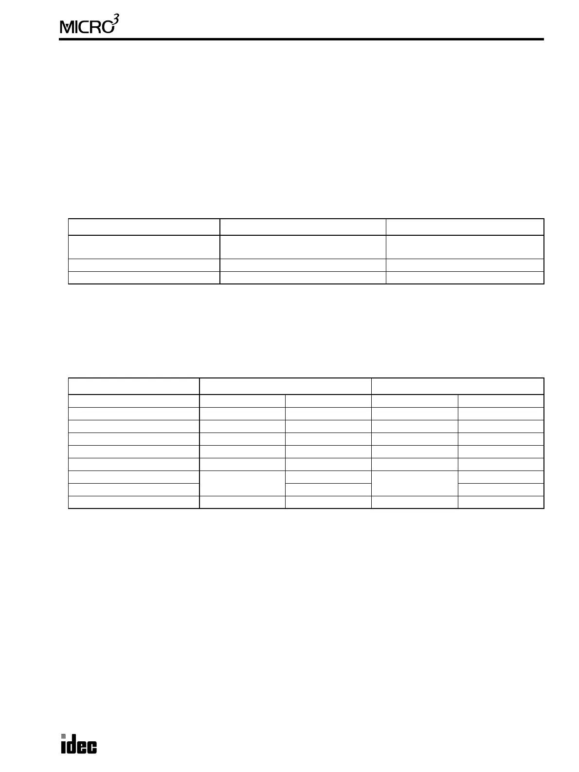
Processing Speed and Program Capacity
LOD, LODN, AND, ANDN, OR, ORN, OUT, OUTN, SET, RST, AND LOD, and OR LOD instructions are processed
faster in the high-speed processing mode. Other instructions do not have to be processed faster in the high-speed process-
ing mode.
The average scan time is not equal to the total of instruction processing times because processing of other than user pro-
gram instructions is involved.
Available Operands and Allocation Numbers
Note: Available input and output numbers depend on the MICRO
3
base unit used.
Limitations on High-speed Processing Mode
Using the high-speed processing mode, the following functions are limited:
• The program capacity is limited to approximately 100 steps.
• Expansion link and data link functions cannot be used.
• Available operand numbers are limited as shown above.
• Control data registers D90 through D99 cannot be used.
High-speed Processing Mode Standard Processing Mode
Processing Time:
Basic Instructions
0.45 µsec average
0.2 µsec minimum
2.2 µsec average
1.2 µsec minimum
Scan Time 400 µsec/100 steps 2.9 msec/1k steps
Program Capacity Approx. 100 steps 1012 steps
High-speed Processing Mode Standard Processing Mode
Input (see note) 14 points I0 to I15 28 points I0 to I35
Output (see note) 10 points Q0 to Q11 20 points Q0 to Q31
Internal Relay 40 points M0 to M47 232 points M0 to M287
Catch Input Relay 8 points M290 to M297 8 points M290 to M297
Special Internal Relay 16 points M300 to M317 16 points M300 to M317
Data Register 32 points D0 to D31 100 points D0 to D99
Timer
16 points total
T0 to T15
32 points total
T0 to T31
Counter C0 to C15 C0 to C31
Shift Register 32 points R0 to R31 64 points R0 to R63