1: GENERAL INFORMATION
USER’S MANUAL 1-15
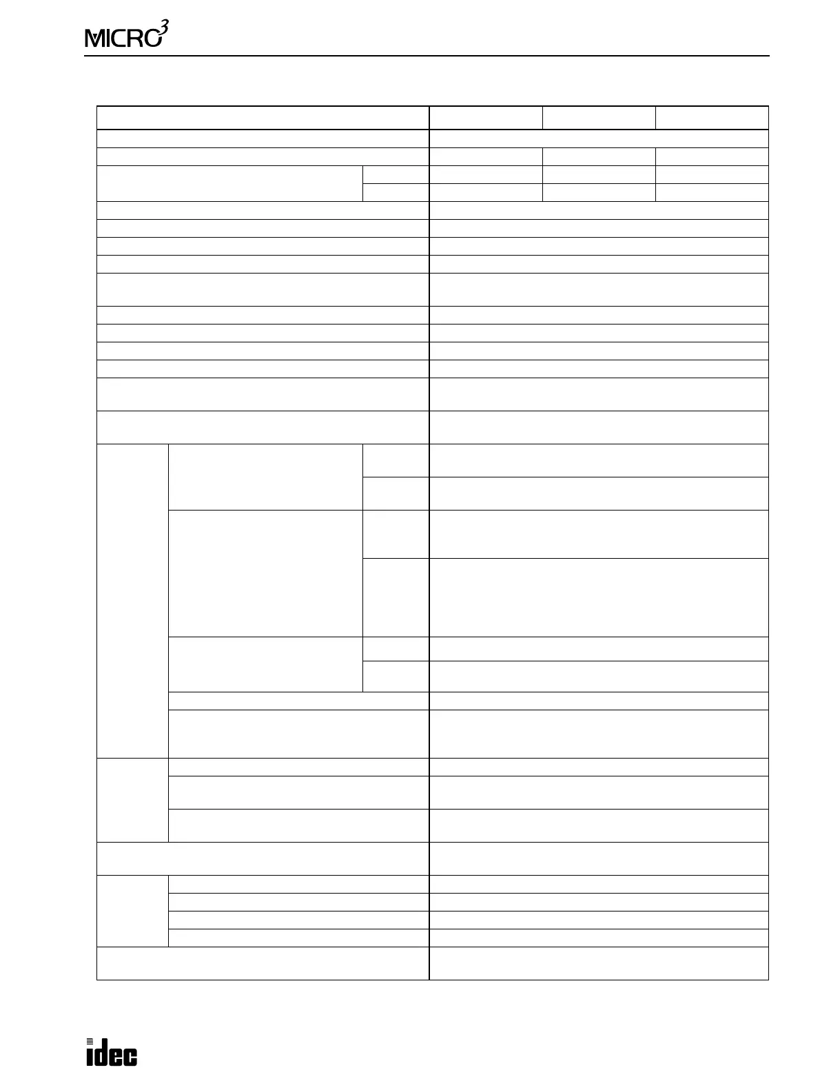
Digital DC Output (Transistor Protect Source Output) Specifications
I/O Type 10-I/O Type 16-I/O Type 24-I/O Type
Output Protection Protected output
Output Points 4 points 7 points 10 points
Output Points per Common Line
COM0 4 points 4 points 5 points
COM1 — 3 points 5 points
Rated Load Voltage 24V DC
Operating Load Voltage Range 19 to 30V DC
Rated Load Current 0.5A per output point
Maximum Load Current 0.625A per output point (at 30V DC)
Voltage Drop (ON Voltage)
1.5V maximum (voltage between COM and output terminals
when output is on)
Inrush Current 5A maximum
Leakage Current 0.1 mA maximum
Clamping Voltage 39V±1V
Maximum Clamping Load 10W
Inductive Load
Continuous operation of T
0.95 = 60 msec (DC13) at 0.5 Hz,
24V DC
External Current Draw
100 mA maximum, 24V DC
(power supply to the –V terminal)
Protected
Output
Protect Activation Current
Q0 &
Q20
0.626 to 0.9A
Q1-Q11
Q21-Q31
0.7 to 1.5A
Restarting Method
Q0 &
Q20
• Remove the cause of overload and turn outputs off for 5
sec using the program loader or CUBIQ on the computer.
• Or, turn power off.
Q1-Q11
Q21-Q31
• Remove the cause of overload, then the output protection
is reset automatically.
Note: When using at a high temperature (45°C or above), it
may take a long time before normal operation is restored. If
this is the case, turn output power off.
Maximum Frequency Response
Test Condition:
Load resistance 1 kΩ, 24V
Q0 10 kHz minimum
Q1-Q31 1 kHz minimum (not including scan time)
PWM Setting Protection function does not work.
Note
The protected output is not reset using FUN20 PLC error
data readout and reset without removing the cause of the
overload.
Isolation
Between Output Terminal and FG 1,500V AC
Between Output Terminal and Internal
Circuit
Photocoupler isolated
Between Output Terminals of Different COM
Lines
Not isolated
Effect of Improper Connection
When a current larger than the rated current flows, perma-
nent damage of output elements may be caused.
Output
Status by
MPU
Operation
Stop OFF
Power Interruption over 25 msec OFF
Power Interruption 25 msec or less ON/OFF status maintained
Power Up OFF until MPU starts to run
Others (IEC 1131-2 Information)
• See Isolation described above.
• See Effect of Improper Connection described above.