1: GENERAL INFORMATION
1-26 USER’S MANUAL
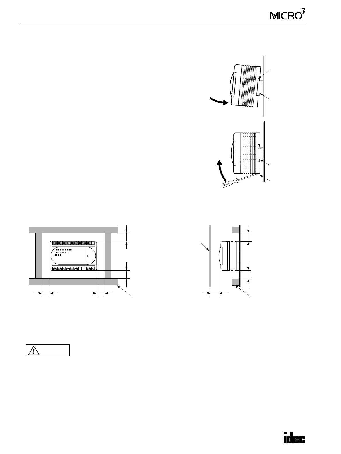
DIN Rail Mounting
The MICRO
3
unit can be mounted on a 35-mm-wide DIN rail.
Applicable DIN rail: IDEC’s BAA1000 (1000mm/39.4" long)
• Mounting on DIN Rail
Fasten the DIN rail to a panel using screws firmly.
Put the groove of the MICRO
3
base unit on the DIN rail, with the input ter-
minal side up, and press the unit to the panel as shown on the right.
Use BNL6 mounting clips on both sides of the MICRO
3
base unit to pre-
vent moving sideways.
• Removing from DIN Rail
Insert a flat screwdriver into the slot in the clamp, pull the screwdriver up,
and turn the MICRO
3
base unit bottom out.
Installation in Control Panel
When wiring input and output lines in ducts, keep a minimum space of 20 mm above and below the MICRO
3
base unit for
maintenance. To prevent excessive heat built-up, keep a minimum space of 20 mm around the MICRO
3
unit for ventilation.
Disposing of the MICRO
3
Units
Unit Groove
35mm-wide
DIN Rail
35mm-wide
DIN Rail
Pull up
Clamp
Wiring Duct
20 mm (0.787")
minimum
20 mm (0.787")
minimum
20 mm (0.787")
minimum
20 mm (0.787")
minimum
20 mm (0.787")
minimum
20 mm (0.787")
minimum
Wiring Duct
Front
Panel
20 mm (0.787")
minimum
Caution
• When disposing of the MICRO
3
units, do so as an industrial waste.
• Dispose of the battery in the MICRO
3
when the battery is dead in accordance with pertaining regu-
lations. When storing or disposing of the battery, use a proper container prepared for this purpose.
This is required when exporting equipment containing MICRO
3
to Europe.
• Dispose of the battery in the memory card when the battery is dead in accordance with pertaining
regulations.