EasyManua.ls Logo

IDEC MICRO3 User Manual

IDEC MICRO3
235 pages
To Next Page IconTo Next Page
To Previous Page IconTo Previous Page
Page #186 background imageLoading...
Page #186 background image
U
SER
S
M
ANUAL
16-1
16: P
ULSE
, A/D C
ONVERSION
I
NSTRUCTIONS
Introduction
The PULS (pulse output) instruction is used to generate pulse outputs of 9.574 Hz through 13,020.8 Hz which can be used
to control pulse motors for simple position control applications. The output pulse ratio is fixed at 50%.
The PWM (pulse width modulation) instruction is used to generate pulse outputs of a 51.2, 25.6, 3.2, or 1.6 msec period
with a variable pulse width ratio between 0% and 100%, which can be used for illumination control.
The PULS and PWM instructions can be used on transistor output type
MICRO
3
base units only.
The A/D (analog/digital conversion) instruction is used to convert an analog value from the A/D converter unit to a digital
value and stores the result to a data register.
91 PULS (Pulse Output)
Key Operation
Valid Operands (Standard Processing)
In the high-speed processing mode, data registers for this instruction are limited to D0 through D31.
While the
MICRO
3
is running, the MODE selection cannot be changed. To change the output pulse frequency during oper-
ation, use a data register as source operand S1, and change the value of the data register. See page 3-16.
When a data register is designated as S1, make sure that the value of the data register does not exceed 249. If the value of
the data register designated as S1 exceeds 249 during operation, a user program execution error will occur, then error indi-
cator ERR1 on the MICRO
3
base unit is lit and special internal relay M304 is also turned on. Correct the program and
transfer the corrected program to the base unit.
When a data register is designated as source operand S1, the data is read as the user program is scanned. When changing
the value of the data register designated as S1, change the value slowly in comparison to the output frequency.
When output Q0 is monitored on the program loader while the PULS instruction is executed, Q0 remains on, and the out-
put indicator also remains on. When input to the PULS instruction is turned off while the pulse output is on, the output is
turned off after a complete pulse is generated.
Output Frequency
Select MODE1 through MODE4 to determine the base frequency. (Do not choose MODE5 and MODE6.)
The output frequency is determined by the following equation:
Operand Function I Q M T C R D Constant Repeat
S1 (Source 1) Pulse width coefficient ——————0-99 0-249
MODE Base Frequency Output Frequency Range (Coefficient 249 through 0)
MODE1 4882.81 Hz 9.574 through 406.901 Hz
MODE2 9765.63 Hz 19.148 through 813.802 Hz
MODE3 78,125 Hz 153.186 through 6510.42 Hz
MODE4 156,250 Hz 306.373 through 13020.8 Hz
When input is on, output Q0 generates a pulse output. The output pulse frequency is deter-
mined by the MODE selection and source operand S1 according to the equation below.
When input is off, output Q0 remains off.
Note: Either the PULS or PWM instruction can be used only once in a user program.
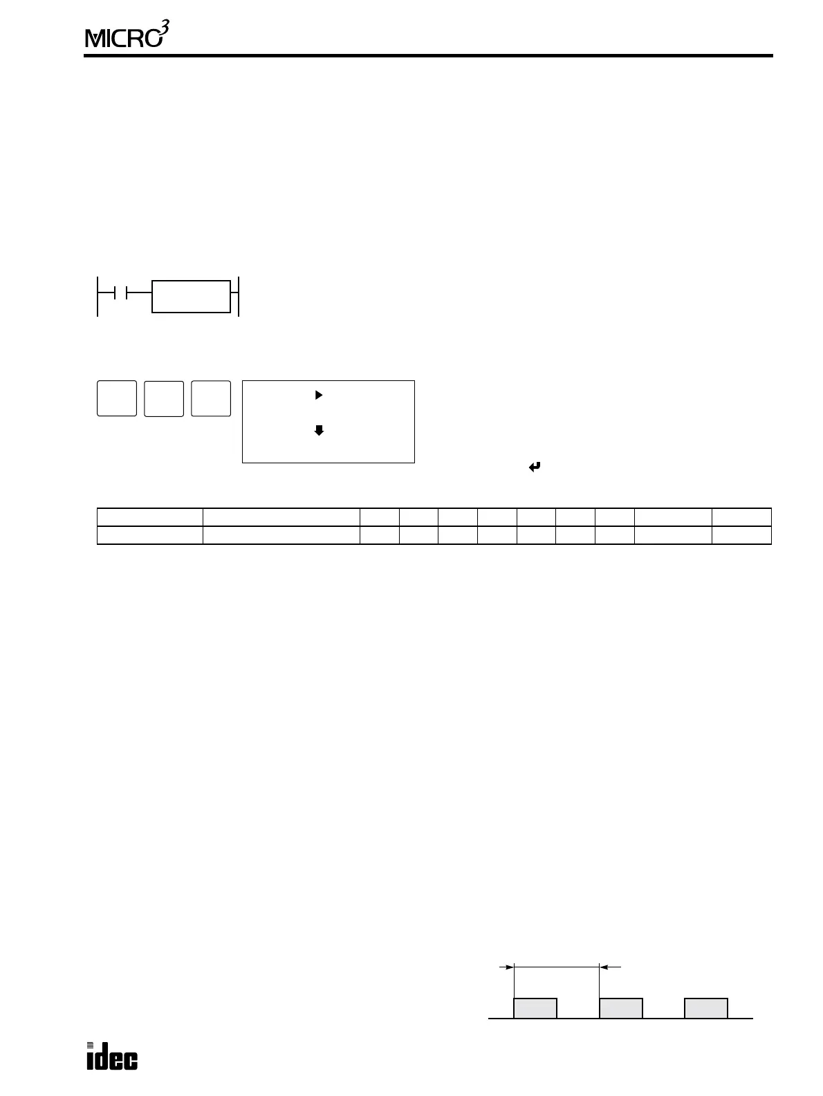
PULS
MODE1
S1
****
ADV
1
BPS
1 S1
PULS (*MODE1)
(Q0)
Enter operand S1 using the LOD/10 key for a decimal con-
stant, or designate a data register.
Select MODE1 through MODE4 using the REP key.
Do not choose MODE5 and MODE6.
To exit, press the key.
9
JMP/E
Output Frequency
Base Frequency (MODE)
(Pulse Width Coefficient S1 + 6) 2×
----------------------------------------------------------------------------------------
Hz[]=
Pulse Width Coefficient S1
Base Frequency (MODE)
Output Frequency 2×
------------------------------------------------------------- 6=
Period
1
Frequency
-------------------------=

Table of Contents

Question and Answer IconNeed help?

Do you have a question about the IDEC MICRO3 and is the answer not in the manual?

IDEC MICRO3 Specifications

General IconGeneral
BrandIDEC
ModelMICRO3
CategoryController
LanguageEnglish

Summary

General Information

Introduction

Provides an overview of general information for understanding MICRO3 functions and specifications.

Features

Highlights the key high-performance functions of the MICRO3 space-saving programmable controller.

Parts Description

Identifies and explains the physical components and terminals of the MICRO3 base unit.

System Setup

Covers basic system configuration, cable connections, off-line programming, and programming tools.

Link Systems

Explains expansion, data, and computer link systems for distributed control and networking.

General Specifications

Lists electrical, environmental, and physical specifications for the MICRO3 unit.

Function Specifications

Details processing modes, I/O capabilities, scan times, memory, and special functions.

Communication and Noise Specs

Covers loader port, data link communication, and noise immunity/emission standards.

Crimping Terminal

Details specifications and usage for crimping terminals for wire connections.

Wiring Diagrams

Provides visual guides for connecting DC and AC power and input signals to the MICRO3.

Output Wiring Diagrams

Illustrates wiring for relay, transistor sink, and transistor protect source outputs.

Dimensions

Shows physical dimensions and mounting hole layouts for the base unit and program loader.

Installation and Disposal

Details installation requirements, methods (direct mounting, DIN rail), and unit disposal procedures.

CHAPTER 2: OPERATION BASICS

Introduction

Describes general information for starting and stopping MICRO3 operation and simple procedures.

Start/Stop Operations

Explains how to start, stop, and reset the MICRO3 unit and monitor its operational status.

Simple Operation and Programming

Guides through connecting the loader, creating, transferring, and monitoring simple user programs.

CHAPTER 3: PROGRAM LOADER

Introduction

Describes general information for understanding the functions and specifications of the program loader.

Parts Description

Identifies the components and features of the FC2A-HL1E program loader.

Operation Modes and Key Usage

Details the Editor, Transfer, Monitor, and FUN modes and how to use the program loader keys.

Programming Procedures

Outlines steps for powering the loader, deleting programs, changing settings, creating, checking, and transferring programs.

Using Editor Mode

Explains how to create, delete, select addresses, and insert instructions in the program editor.

Transfer Operations

Covers writing, reading, and comparing programs between loader, base unit, and memory card.

Memory Card Operations

Details identifying, formatting, installing, and restoring system programs on the memory card.

Using Monitor Mode

Explains how to monitor I/O, relays, timers, counters, and data registers.

Setting and Resetting

Details how to SET/RST inputs, outputs, and internal relays using the program loader.

FUN Settings

Describes various FUN settings for CPU configuration, program loader, and memory card.

CHAPTER 4: SPECIAL FUNCTIONS

Introduction

Introduces special functions like high-speed processing, catch input, pulse output, counters, and link functions.

High-speed Processing & Input Features

Covers high-speed processing mode, catch input function, and input filter function.

Output & Counter Functions

Explains Pulse Output, PWM, and High-speed Counter instructions for precise control.

Link Functions

Details Expansion Link, Data Link, and Computer Link systems for networking and distributed control.

Analog Functions

Covers External Analog Timer, Analog Input, and Analog Output functions for signal processing.

CHAPTER 5: CPU CONFIGURATION (FUN)

Introduction

Describes setting the FUN (function) table for user program configuration.

FUN Settings Overview

Provides an overview of FUN settings for program configuration, status monitoring, and loader operation.

Key Operation

Describes how to navigate and select FUN settings using the program loader keys.

Specific FUN Settings

Details individual FUN settings from FUN1 to FUN50 for comprehensive device configuration.

CHAPTER 6: ALLOCATION NUMBERS

Introduction

Describes allocation numbers available for programming basic and advanced instructions.

Allocation Numbers

Lists available I/O, internal relays, timers, counters, and data registers for standard and high-speed modes.

Special Internal Relays

Details the functions of special internal relays M290 through M317 for specific operations.

CHAPTER 7: BASIC INSTRUCTIONS

Introduction

Describes programming of basic instructions, available operands, and sample programs.

Basic Instruction List

Provides a comprehensive list of basic instructions, their symbols, functions, and address requirements.

Logic, Load, and Stack Instructions

Explains instructions like LOD, OUT, AND, OR, AND LOD, OR LOD, BPS, BRD, BPP for basic logic and stack operations.

Timers and Counters

Covers the usage and parameters of TIM, TMH, TMS timers, and CNT, CC=, CC>= counters.

Shift Registers

Explains SFR, SFRN, and Bidirectional Shift Register instructions for data shifting.

Special Output and Control Instructions

Covers SOTU, SOTD, MCS/MCR, JMP/JEND, SET/RST, and END instructions for program control.

CHAPTER 8: ADVANCED INSTRUCTIONS

Introduction

Describes advanced instruction menus, operands, formats, and data types.

Instruction Menus and Structure

Explains advanced instruction menus, list, structure, input conditions, and operand usage.

Programming and Revision

Details how to program, revise, and use repeat operations for advanced instructions via the loader.

CHAPTER 9: MOVE INSTRUCTIONS

Introduction

Introduces instructions for moving data: MOV, MOVN, IMOV, IMOVN.

Move Instructions

Explains MOV, MOVN, IMOV, and IMOVN for transferring data between registers and I/O.

Repeat Operation and Examples

Details using repeat operations with source and destination operands and provides practical examples.

CHAPTER 10: COMPARISON INSTRUCTIONS

Introduction

Describes comparing data using instructions like equal to, unequal to, less than, and greater than.

Comparison Instructions

Explains CMP=, CMP<>, CMP<, CMP>, CMP<=, and CMP>= instructions for value comparison.

Repeat Operation and Examples

Details using repeat operations with operands and demonstrates examples of CMP instructions.

CHAPTER 11: BINARY ARITHMETIC INSTRUCTIONS

Introduction

Covers binary arithmetic instructions for computation using addition, subtraction, multiplication, and division.

Arithmetic Instructions

Explains ADD, SUB, MUL, and DIV instructions for performing binary arithmetic operations.

Carry/Borrow Handling and Repeat Ops

Covers M303 for carry/borrow signals, repeat operations, and examples for arithmetic instructions.

CHAPTER 12: BOOLEAN COMPUTATION INSTRUCTIONS

Introduction

Introduces Boolean computations using AND, OR, and exclusive OR statements.

Boolean Computation Instructions

Explains ANDW, ORW, and XORW instructions for performing bitwise Boolean operations on words.

Repeat Operation and Example

Details using repeat operations with operands and demonstrates an example of XORW instruction.

CHAPTER 13: BIT SHIFT / ROTATE INSTRUCTIONS

Introduction

Explains bit shift and rotate instructions for shifting 16-bit data in data registers.

Shift and Rotate Instructions

Explains SFTL (Shift Left), SFTR (Shift Right), ROTL (Rotate Left), and ROTR (Rotate Right) instructions.

Bidirectional Shift Register

Describes creating a bidirectional shift register using SFR and SFRN instructions.

Examples

Demonstrates examples of SFTL, SFTR, ROTL, and ROTR instructions with practical usage.

CHAPTER 14: CLOCK / CALENDAR INSTRUCTIONS

Introduction

Introduces instructions for programming the real-time calendar and clock.

Calendar and Clock Instructions

Covers CALR, CALW, CLKR, CLKW, and ADJ instructions for reading and setting time and date.

Examples

Provides examples for CLKW, ADJ, and Time Scheduled Control using clock/calendar data.

CHAPTER 15: INTERFACE INSTRUCTIONS

Introduction

Describes instructions for interfacing with display units, digital switches, and analog potentiometers.

Interface Instructions

Details DISP (display), DGRD (digital read), ANR0/ANR1 (analog read) instructions.

Examples

Illustrates examples of DISP, DGRD, and ANR0 instructions for practical interface usage.

CHAPTER 16: PULSE, A/D CONVERSION INSTRUCTIONS

Introduction

Introduces instructions for pulse output, PWM, and analog-to-digital conversion.

Pulse Output Instructions

Explains PULS for pulse output and PWM for pulse width modulation for motor control.

A/D Conversion Instruction

Describes the A/D instruction for converting analog signals to digital values.

Examples

Provides examples for PULS, PWM, and A/D conversion instructions.

CHAPTER 17: HIGH-SPEED COUNTER INSTRUCTIONS

Introduction

Describes high-speed counter functions for position control and motor control.

Specifications and Instructions

Lists HSC specifications and details HSC0, HSC1, HSC2, and HSC3 instructions.

Examples

Demonstrates examples of HSC0, HSC1, HSC2, and HSC3 instructions with practical scenarios.

CHAPTER 18: TROUBLESHOOTING

Introduction

Describes procedures to determine causes of trouble and actions for taking when any trouble occurs.

Error Indicators and Messages

Explains ERR1/ERR2 indicators, reading error codes, error messages, and general error codes.

Error Causes and Actions

Details specific error codes, their causes, and recommended actions for resolution.

Troubleshooting Diagrams

Provides visual flowcharts to diagnose and resolve common operational issues.

APPENDIX

Execution Times

Lists the maximum execution times for various instructions in standard and high-speed processing modes.

END Processing Time Breakdown

Details the breakdown of time components contributing to the END instruction's processing time.

Type List

Lists MICRO3 CPU base units, expansion I/O, and program loader types with their specifications.

Cables and Accessories

Lists available cables, accessories, and adapters for the MICRO3 system and program loader.

Related product manuals