15: I
NTERFACE
I
NSTRUCTIONS
U
SER
’
S
M
ANUAL
15-5
83 ANR0 (Analog Read 0)
84 ANR1 (Analog Read 1)
Note:
Analog potentiometer 0 is provided on all models of
MICRO
3
and
MICRO
3
C
. Analog potentiometer 1 is provided on
16- and 24-I/O
MICRO
3
base units. So, ANR0 can be used on all models. ANR1 can be used on 16- and 24-I/O
MICRO
3
only; not on
MICRO
3
C
and 10-I/O
MICRO
3
.
Key Operation
Press the ADV key, followed by the advanced instruction number.
Valid Operands (Standard Processing)
In the high-speed processing mode, data registers for these instructions are limited to D0 through D31.
Since the ANR0 and ANR1 instructions are executed in each scan while input is on, a pulse input from an SOTU or SOTD
instruction should be used as required.
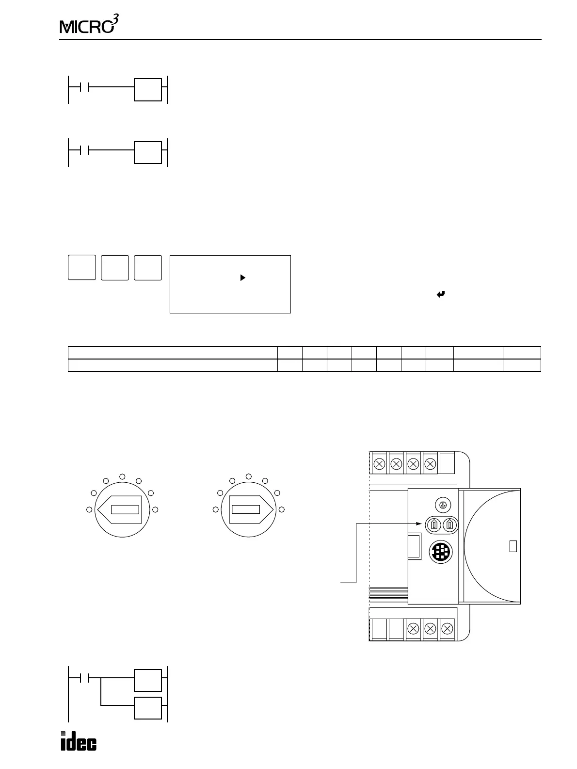
Analog Potentiometer Setting
The analog potentiometer positions and set values are shown below:
Example: ANR0
Operand Function I Q M T C R D Constant Repeat
Destination to store the analog potentiometer value ——————0-99 — —
When input is on, the value (0 through 249) set with analog potentiometer 0 is read to the
data register designated as destination. This instruction is useful for adjusting preset values
of timer (TIM, TMH, and TMS) and pulse (PULS and PWM) instructions.
ANR0
****
When input is on, the value (0 through 249) set with analog potentiometer 1 is read to the
data register designated as destination. This instruction is useful for adjusting preset values
of timer (TIM, TMH, and TMS) and pulse (PULS and PWM) instructions.
ANR1
****
ADV
0 LOD I 0
1 ANR0
2 END
3 END
Enter a data register operand number for the ANR0 or
ANR1 instructions to store data read from analog potenti-
ometer 0 or 1.
To enter the instruction, press the key.
Note: The ANR0 and ANR1 instructions can be used only
once each in a user program.
8
MCS/R
3
BPP
Turned Fully to the Left
Minimum Value = 0
Turned Fully to the Right
Maximum Value = 249
Analog Potentiometer
The 10-I/O type MICRO
3
and all MICRO
3
C have one potentiometer.
The 16- and 24-I/O type MICRO
3
have two potentiometers: analog
potentiometer 0 on the left and analog potentiometer 1 on the right.
01
7
3
4
5
62
1
0
When input I0 is on, the value from analog potentiometer 0 is read to data register D80 and
is used as a preset value for timer TIM7.
I0
ANR0
D80
TIM7
D80