7: BASIC INSTRUCTIONS
USER’S MANUAL 7-27
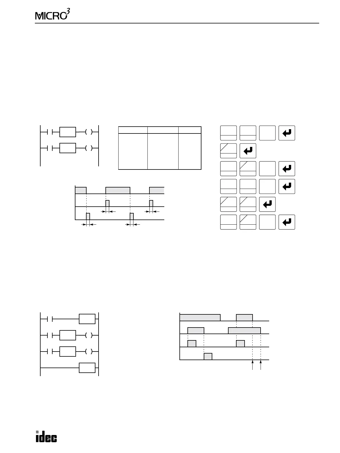
SOTU and SOTD (Single Output Up and Down)
The SOTU instruction “looks for” the transition of a given input from off to on. The SOTD instruction looks for the transi-
tion of a given input from on to off. When this transition occurs, the desired output will turn on for one scan. The SOTU or
SOTD instruction converts an input signal to a “one-shot” pulse signal. The SOTU or SOTD instruction is followed by one
address.
SOTU and SOTD instructions can be used repeatedly.
If operation is started while the given input is already on, the SOTU output will not turn on. The transition from off to on is
what triggers the SOTU instruction.
When a relay of the relay output type MICRO
3
base unit is defined as the SOTU or SOTD output, it may not operate if the
scan time is not compatible with relay requirements.
There is a special case when the SOTU and SOTD instructions are used between the MCS and MCR instructions (which
are detailed on page 7-28). If input I2 to the SOTU instruction turns on while input I1 to the MCS instruction is on, then
the SOTU output turns on. If input I2 to the SOTD instruction turns off while input I1 is on, then the SOTD output turns
on. If input I1 turns on while input I2 is on, then the SOTU output turns on. However, if input I1 turns off while input I2 is
on, then the SOTD output does not turn on as shown below.
I0
I0
Ladder Diagram
Key Operation
LOD
10
SET
I
OUT
16
RST
F
Q
Prgm Adrs Instruction Data
0
1
2
3
4
5
LOD
SOTU
OUT
LOD
SOTD
OUT
I0
Q0
I0
Q1
Program List
Input I0
ON
OFF
Output Q0
ON
OFF
Output Q1
ON
OFF
Timing Chart
SET
I
Q1
LOD
10
0
Note: Pressing the SOT key on the pro-
gram loader programs the SOTU or
SOTD instruction alternately.
SOTU
Q0
SOTD
SOT
C
M
0
OUT
16
RST
F
Q
0
SOT
C
M
SOT
C
M
1
BPS
T
T T
T
Note: “T” equals one scan time (one-shot pulse).
I2
I1
Ladder Diagram
Input I1
ON
OFF
SOTU Output M1
ON
OFF
SOTD Output M2
ON
OFF
Timing Chart
M2
MCS
SOTD
MCR
No Output No Output
I2
M1
SOTU
Input I2
ON
OFF