7: BASIC INSTRUCTIONS
7-26 USER’S MANUAL
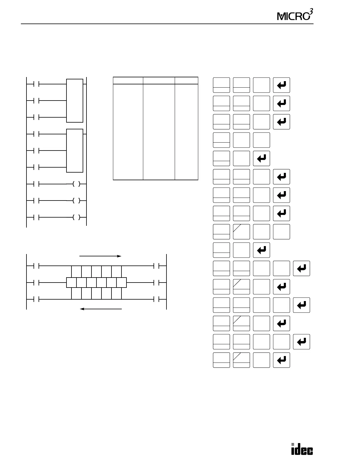
Bidirectional Shift Register
A bidirectional shift register can be created by first keying in the SFR instruction, complete with two addresses, as detailed
in the Forward Shift Register section on page 7-23. Next, the SFR and NOT instructions are keyed in, complete with two
addresses, as detailed in the Reverse Shift Register section on page 7-25.
I2
I1
Ladder Diagram
Key Operation
LOD
10
SET
I
Prgm Adrs Instruction Data
0
1
2
3
5
6
7
8
10
11
12
13
14
15
LOD
LOD
LOD
SFR
LOD
LOD
LOD
SFR NOT
LOD
OUT
LOD
OUT
LOD
OUT
I1
I2
I3
22
6
I4
I5
I6
22
6
R23
Q0
R24
Q1
R26
Q2
Program List
R22
6
1
BPS
Reset
Pulse
LOD
10
SET
I
LOD
10
2
BRD
I3
Data
LOD
10
SET
I
SFR
R
R23
R24
R26
LOD
10
SFR
R
OUT
16
RST
F
Q
LOD
10
SFR
R
OUT
16
RST
F
Q
LOD
10
SFR
R
OUT
16
RST
F
Q
1
BPS
2
BRD
2
BRD
3
BPP
Q0
Q1
Q2
I5
I4
R22
N6
Reset
Pulse
I6
Data
Structural Diagram
I3
I1
R22
Reset
Data
I2
Pulse
R23R24 R25
Forward Shifting
Last Bit: 22 # of Bits: 6
R26 R27
Note: Output is initiated only for those bits highlighted in bold print.
I4
I6
I5
Reset
Data
Pulse
First Bit: 22 # of Bits: 6
Reverse Shifting
LOD
10
SET
I
LOD
10
SET
I
LOD
10
LOD
10
SET
I
SFR
R
4
2
BRD
2
BRD
NOT
A
6
CC>=
2
BRD
2
BRD
6
CC>=
2
BRD
3
BPP
0
4
2
BRD
6
CC>=
5
CC=
6
CC>=