1: GENERAL INFORMATION
USER’S MANUAL 1-7
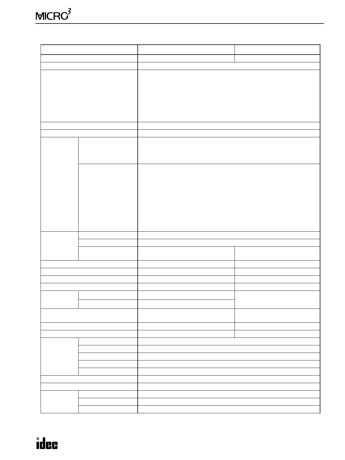
Function Specifications
Mode Standard Processing High-speed Processing
Program Capacity 1012 steps Approx. 100 steps
User Program Memory EEPROM, RAM (backed up by battery)
Backup Function
A user program is transferred from the program loader through the CPU to
RAM and EEPROM in the MICRO
3
. The user program and data in the RAM are
backed up by a lithium secondary battery.
If the contents in the RAM are destroyed after a power failure longer than the
specified value, the user program is transferred from the EEPROM to the
RAM automatically at power up, and is not erased. However, since data is
destroyed, the user is alerted with an error message (keep data sum check
error, etc.).
Control System Stored program system (not in compliance with IEC1131-3)
Programming Method Logic symbol
Instruction
Words
Basic Instruction
28 basic instructions
LOD, LODN, OUT, OUTN, SET, RST, AND, ANDN, OR, ORN, AND LOD,
OR LOD, BPS, BRD, BPP, TIM, CNT, CC=, CC
≥, SFR, SFRN, SOTU, SOTD, JMP,
JEND, MCS, MCR, END
Advanced Instruction
MICRO
3
: 38 advanced instructions
NOP, MOV, MOVN, IMOV, IMOVN, CMP=, CMP<>, CMP<, CMP>, CMP<=,
CMP>=, ADD, SUB, MUL, DIV, ANDW, ORW, XORW, SFTL, SFTR, ROTL, ROTR,
CLS4, CALW, CLKR, CLKW, ADF, DISP, DGRD, ANR0, ANR1, PULS, PWM, A/D,
HSC0, HSC1, HSC2, HSC3
MICRO
3
C: 40 advanced instructions
NOP, MOV, MOVN, IMOV, IMOVN, CMP=, CMP<>, CMP<, CMP>, CMP<=,
CMP>=, ADD, SUB, MUL, DIV, ANDW, ORW, XORW, SFTL, SFTR, ROTL, ROTR,
CLS4, CALW, CLKR, CLKW, ADF, DISP, DGRD, ANR0, PULS, PWM, A/D, HSC0,
HSC1, HSC2, HSC3, TXD, RXD, CMP2
I/O
Input Points 6 points (10-I/O type), 9 points (16-I/O type), 14 points (24-I/O type)
Output 4 points (10-I/O type), 7 points (16-I/O type), 10 points (24-I/O type)
Expansion I/O
One expansion station can be added.
Maximum I/O is 48 points.
———
Data Link Possible with 6 slave stations ———
Scan Time 2.9 msec average/1K steps 400 µsec average/100 steps
Processing Time (basic instruction) 2.2 µsec average 0.45 µsec average
Internal Relay 232 points 40 points
Data
Register
MICRO
3
100 points
32 points
MICRO
3
C
500 points
Control Data Register
10 points
(designated from data registers)
———
Shift Register 64 points 32 points
Counter/Timer 32 points total 16 points total
Counter/
Timer
Presets
Adding Counter 0 to 9999
Reversible Counter 0 to 9999
1-msec Timer 1 msec to 9.999 sec
10-msec Timer 10 msec to 99.99 sec
100-msec Timer 100 msec to 999.9 sec
Catch Input Relay 8 points
Special Internal Relay 16 points
Catch Input
Points 8 points
Must Turn ON Pulse 40 µsec minimum (when hard filter is set to 10)
Must Turn OFF Pulse 150 µsec minimum (when hard filter is set to 10)