USER’S MANUAL 9-1
9: MOVE INSTRUCTIONS
Introduction
Data can be moved using the MOV (move), MOVN (move not), IMOV (indirect move), or IMOVN (indirect move not)
instruction. The moved data is 16-bit word data, and the repeat operation can also be used to increase the quantity of data
moved. In the MOV or MOVN instruction, the source and destination operand are designated by S1 and D1 directly. In the
IMOV or IMOVN instruction, the source and destination operand are determined by the offset values designated by S2 and
D2 added to source operand S1 and destination operand D1.
Since the move instructions are executed in each scan while input is on, a pulse input from an SOTU or SOTD instruction
should be used as required.
11 MOV (Move)
Key Operation
Valid Operands (Standard Processing)
In the high-speed processing mode, operands for advanced instructions are limited. See page 6-1.
When T (timer) or C (counter) is used as S1, the timer/counter current value is read out. When T (timer) or C (counter) is
used as D1, the data is written in as a preset value which can be 0 through 9999.
When a bit operand such as input, output, internal relay, or shift register is used as the source or destination, 16 points are
used. When repeat is designated for a bit operand, the quantity of operand bits increases in 16-point increments.
Examples: MOV
Operand Function I Q M T C R D Constant Repeat
S1 (Source 1) Operand to move 0-35 0-31 0-317 0-31 0-31 0-63 0-99 0-65535 1-31
D1 (Destination 1) Operand to move to — 0-31 0-287 0-31 0-31 0-63 0-99 — 1-31
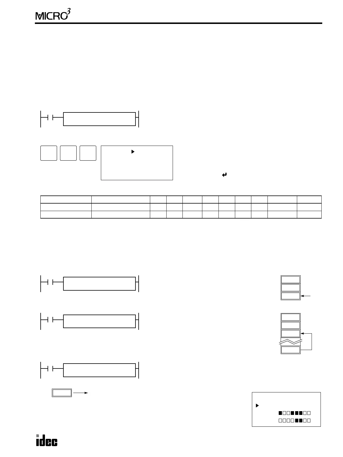
MOV S1(R)
*****
REP
**
D1(R)
****
S1 → D1
When input is on, 16-bit word data from operand designated by S1 is moved
to operand designated by D1.
ADV
1
BPS
1
BPS
1 S1
MOV
D1:
Enter operands S1 and D1.
When repeat is required, press the REP key for the operand
to repeat, and enter the number of repeat cycles.
To exit, press the key.
I0
MOV REP
**
810 → D2
When input I0 is on, constant 810 designated by
source operand S1 is moved to data register D2
designated by destination operand D1.
D1
D0
810
D2
810
S1
810
D1
D2
I1
MOV REP
**
D10 → D2
When input I1 is on, the data in data register D10
designated by source operand S1 is moved to data
register D2 designated by destination operand D1.
D1
D0
930
D2
930
D10
S1
D10
D1
D2
I2
MOV REP
**
D10 → M0
When input I2 is on, the data in data register D10 designated by source
operand S1 is moved to 16 internal relays starting with M0 designated by
destination operand D1.
12345
D10
S1
D10
D1
M0
MON
D 10 12345
M 0
M 10
M0 through M7, M10 through M17
The data in the source data register is converted into 16-bit binary data, and the ON/OFF
statuses of the 16 bits are moved to internal relays M0 through M7 and M10 through M17.
M0 is the LSB (least significant bit). M17 is the MSB (most significant bit). When D0, M0,
and M10 are monitored on the program loader, the data is displayed as shown on the right.