5: CPU CONFIGURATION (FUN)
USER’S MANUAL 5-11
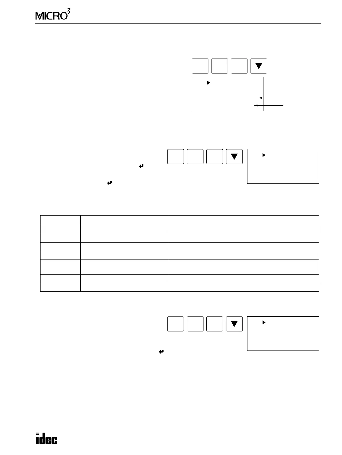
FUN25: Scan Time Readout
The scan time of the user program in the MICRO
3
base unit can be read using FUN25.
The current value of the scan time is displayed in units of
msec and updated periodically. The maximum value of the
scan time is shown in parentheses on the bottom line.
The current and maximum values of the scan time are dis-
played in the decimal notation for the integer and in the octal
notation for the fraction. In the example on the right, the
actual current value is 0.7 × 1.25 = 0.875 msec, and the maxi-
mum value is 1 + 0.5 × 1.25 = 1.625 msec.
To return to the editor mode, press the CLR key.
The current value of the scan time is stored in control data register D99, if enabled using FUN10. See page 5-8.
FUN26: Operand Data Clear
The data of all or selected operand can be cleared
using FUN26.
To clear the data of all operands, press the key.
To select an operand, move the cursor down, and
press the REP key. Press the key to clear the data
of the selected operand.
When the data is cleared, “END” is displayed.
When this command is executed the following data is cleared.
To return to the editor mode, press the CLR key.
FUN27: Link Formatting Sequence
When the expansion link or data link configuration is
changed, execute the link formatting sequence from
the master station using FUN27 to initialize the link
communication line.
To initialize the link communication line, press the key.
The
MICRO
3
base unit with the function selector switch set to zero is used for the base station in the expansion link system
or the master station in the data link system. When the base or master station is powered up, the base or master station
sends the link formatting sequence to confirm whether the expansion station or slave stations can be communicated with.
If the expansion station or any slave station is not powered up, the expansion or slave station is not recognized. To enable
communication with this expansion or slave station, power up the station, and execute FUN27 from the base or master sta-
tion to initialize the link communication line.
To return to the editor mode, press the CLR key.
Selection Operand Data Cleared
ALL All operands (Q, M, R, C, T, D) All data shown below are cleared.
Q Output All outputs are turned off.
M Internal relay All internal relays are turned off.
R Shift register All shift register bits are turned off.
C Counter
CNT0 and 1: Current values are cleared to the preset value.
CNT2 to 31: Current values are cleared to zero.
T Timer All timer current values are cleared.
D Data register Data of all data registers are cleared to zero.
FUN
FUN 25 SCAN
SCAN TIME 0.7ms
( 1.5)
2
BRD
5
CC=
Current Value
Maximum Value
FUN
FUN 26 DATA-CLR
*ALL Operand CLR
OK?
2
BRD
6
CC>=
FUN
FUN 27 D-LINK
Data Link
Setting OK?
2
BRD
7
END