17: HIGH-SPEED COUNTER INSTRUCTIONS
17-6 USER’S MANUAL
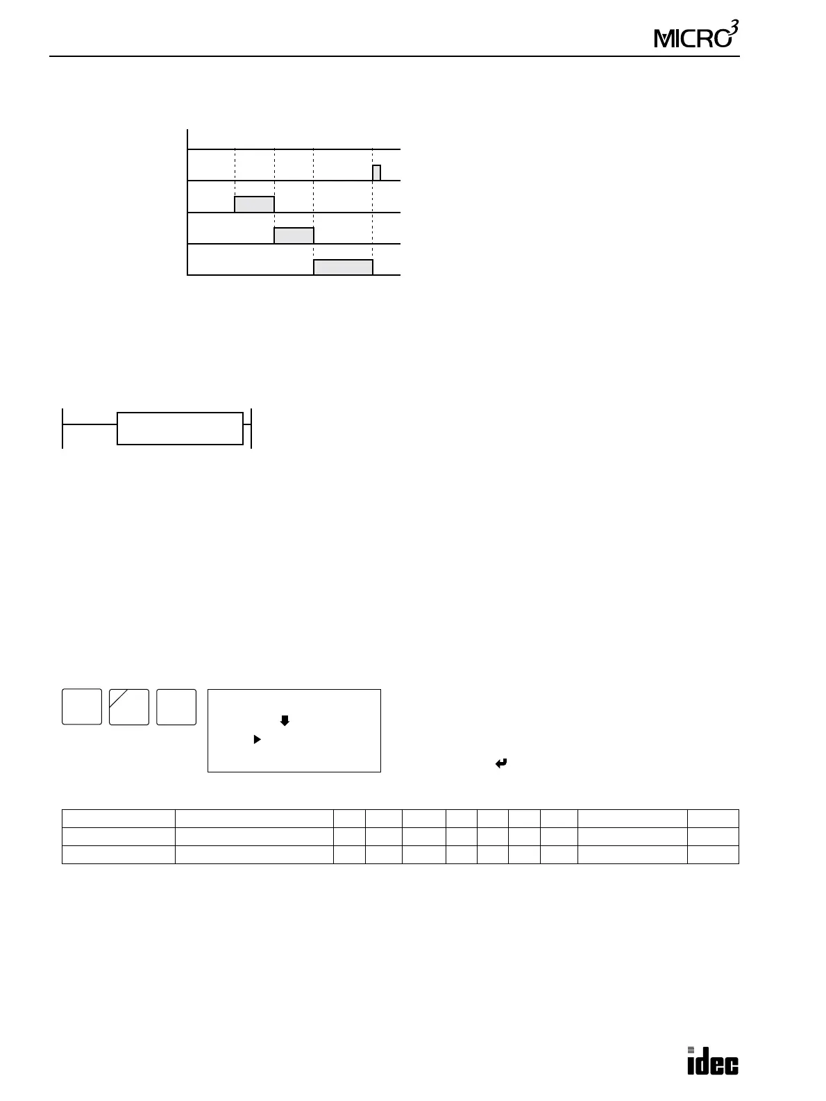
Example: HSC1, continued
A3 HSC2 (Pulse Output Control)
The high-speed counter current value is reset to 0 when MICRO
3
is powered up. The high-speed counter holds the current
value while MICRO
3
is stopped and restarts counting input pulses starting with the existing current value. Include the hard
reset or soft reset in the user program, if necessary.
Note: Since the PULS instruction can be used on transistor output type MICRO
3
base units only, the HSC2 instruction can
also be used on transistor output type MICRO
3
base units only.
Note: Only one of HSC0 through HSC3 and A/D instructions can be used only once in a user program.
Key Operation
Valid Operands (Standard Processing)
In the high-speed processing mode, operands for advanced instructions are limited. See page 6-1.
Allocation Numbers
The HSC2 instruction uses the following input and internal relay numbers:
Pulse input: Input I0
Hard reset input: Input I1
Soft reset special internal relay: Internal relay M315 (When M315 is on, the current value is reset to 0.)
Operand Function I Q M T C R D Constant Repeat
S1 (Source 1) Preset value — — — — — — 0-99 1-4,294,967,295 —
D1 (Destination 1) High-speed counter output — 0-31 0-287 — — — — — —
Output Q2
ON
OFF
ON
OFF
Output Q1
ON
OFF
10,000
HSC1 Current Value
50,000 100,000
Output Q0
ON
OFF
Hard Reset Input I1
0
High-speed counter HSC1 counts input pulses to input
I0. When the first preset value 10,000 is reached, output
Q0 is turned on. When the second preset value 50,000 is
reached, output Q0 is turned off, and output Q1 is turned
on. When the last preset value 100,000 is reached, output
Q1 is turned off, and output Q2 is turned on. Output Q2
remains on until hard reset input I1 is turned on to reset
the high-speed counter (hard reset is set to HIGH).
Since this example does not include the soft reset special
internal relay to reset at startup, the current value is held
when MICRO
3
is stopped.
For monitoring high-speed counter preset and current
values, see page 3-15.
The HSC2 instruction is used with the PULS (pulse output) instruction to generate a
predetermined number of pulse outputs. The PULS instruction generates high-fre-
quency output pulses at output Q0. By hard-wiring output Q0 to input I0, HSC2
counts input pulses to input I0. (Input pulses can also be entered to input I0 from
another source.) When the HSC2 current value is equal to or greater than the preset
value designated by source operand S1, the output or internal relay designated by
destination operand D1 is turned on, and the pulse output at output Q0 is stopped.
D1
****
S1
****
HSC2
LOW
ADV
0 (I0)
HSC2
S1
D1: (*---)
Enter operands S1 and D1.
To select hard reset mode from LOW, HIGH, or unused,
press the REP key.
To exit, press the key.
NOT
A
3
BPP