17: HIGH-SPEED COUNTER INSTRUCTIONS
USER’S MANUAL 17-7
Hard Reset Selection
Input I1 can be used to reset the current value of high-speed counter HSC2.
LOW: Resets the current value when input I1 is turned off. HSC2 is enabled while I1 is on.
HIGH: Resets the current value when input I1 is turned on. HSC2 is enabled while I1 is off.
*–––: Disables hard reset. (Input I1 can be used as an ordinary input.)
Soft Reset Special Internal Relay M315
In addition to the hard reset using input I1, the high-speed counter cur-
rent value can be reset by turning special internal relay M315 on using
another input, output, or internal relay. M315, if used, must be pro-
grammed immediately after the HSC2 instruction as shown on the right.
Preset Value
The preset value can be 1 through 4,294,967,295 (FFFF FFFFh), which is designated using a constant or two consecutive
data registers. The first data register designated by source operand S1 stores the upper digits, and the next data register
stores the lower digits. To enter a double-word value to two consecutive data registers using the program loader, from the
editor mode press the MON, D, data register number, ADV, followed by the LOD/10 (decimal) or OUT/16 (hexadecimal),
data register value, and keys. See page 3-16. If the preset value designated by a data register is changed during high-
speed counter operation, the high-speed counter remains unchanged for that cycle. The change will be reflected in the next
count cycle after resetting.
Input Filter and Input Frequency
MICRO
3
has hard and soft filter functions. Only the hard filter works on high-speed counter instructions. The hard filter set-
tings affect the input response. See page 4-3. The maximum input frequency for the HSC2 instruction is 5 kHz (4 kHz
when using the program loader).
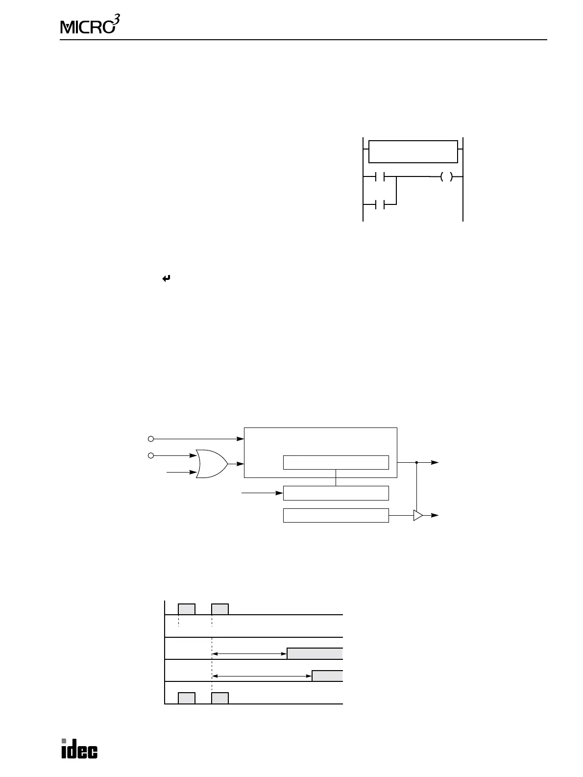
Block Diagram (HSC2: Pulse Output Control)
HSC2 counts input pulses to input I0. When the preset value is reached, comparison output is turned on, and pulse output
Q0 is turned off. The pulse output frequency is determined by the PULS (pulse output) instruction.
Output Delay (HSC2: Pulse Output Control)
After the HSC2 has counted the Nth input pulse (the preset value), the output or internal relay designated by destination
operand D1 is turned on with a delay shown below.
M301 is the initial-
ize pulse special
internal relay.
HSC2
****
S1 D1
M100100
M301
I10
M315
Pulse Input I0
Hard Reset Input I1
Soft Reset M315
Pulse
Reset
32-bit Comparison Register
32-bit Counter
Comparison Output
Preset Value
Pulse Output
Pulse Output Q0
When the preset value is reached,
the pulse output is turned off.
Pulse Input I0
ON
OFF
Output Pulse
ON
OFF
Comparison Result
ON
OFF
N–1
HSC2 Current Value
N
(D1 = Output)
190 µsec maximum
T
e output pu
se stop s
gna
s turne
on
µsec at the maximum after the current value
reaches the preset value.
The example on the left shows the operation
when the PULS instruction generates
4882.81-Hz output pulses.
Note: When
MICRO
3
is restarted without reset-
ting the HSC2 after the preset value has been
reached, the comparison result output or inter-
nal relay is reset, and the HSC2 continues to
count input pulses starting with the preset value.
300 µsec maximum
ON
OFF
Pulse Output Q0
Stop Signal