7: BASIC INSTRUCTIONS
USER’S MANUAL 7-5
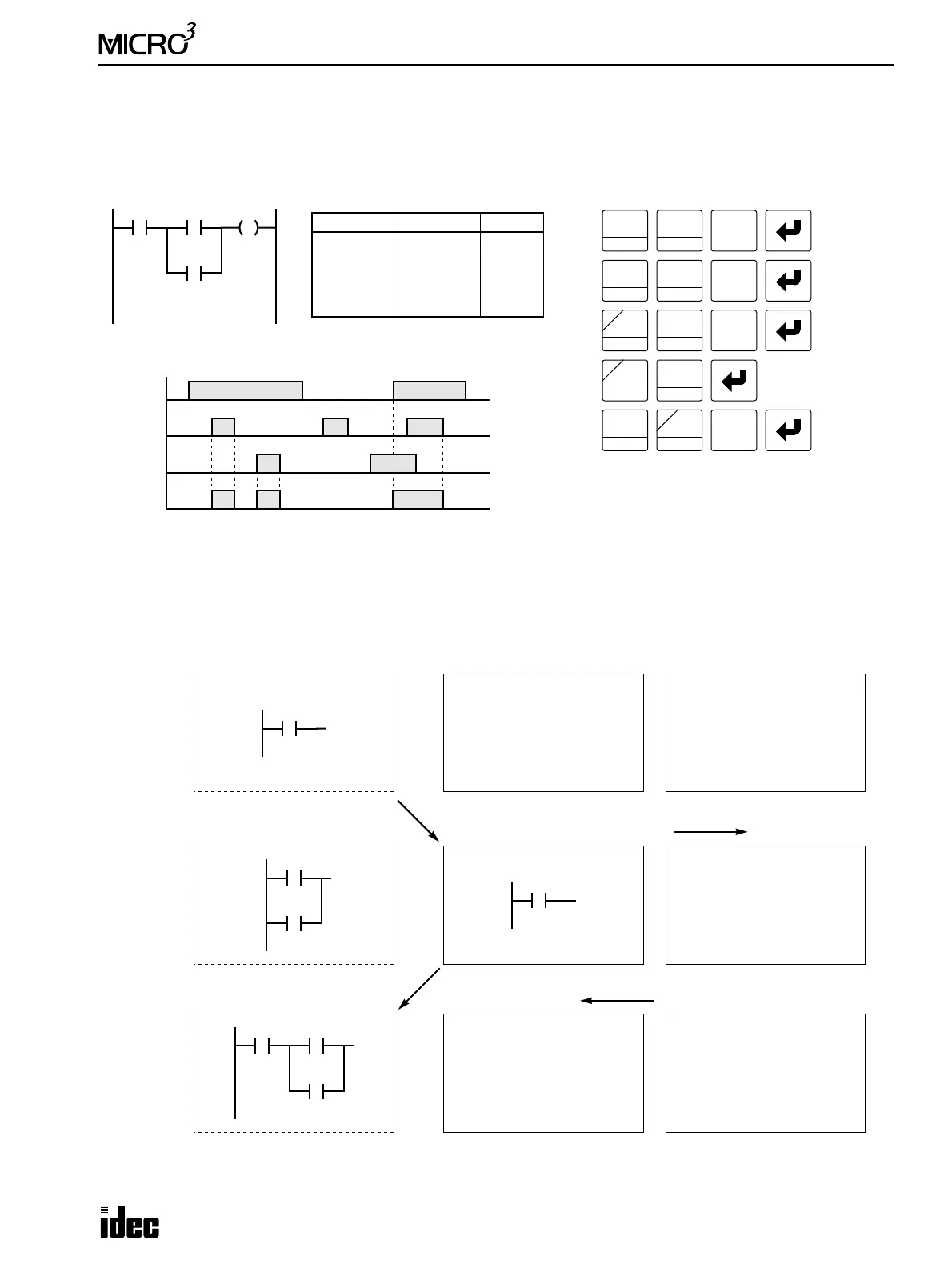
AND LOD (Load)
The AND LOD instruction is used to connect, in series, two or more circuits starting with the LOD instruction. The AND
LOD instruction is the equivalent of a “node” on a ladder diagram. The AND LOD instruction is keyed after entering those
circuits to be connected.
The AND LOD (load) instruction reads programs stored in the stack register by the LOD or LODN instruction and then
AND’s them.
Ladder Diagram
Key Operation
I0
LOD
10
SET
I
Q0
0
OUT
16
RST
F
Q
Prgm Adrs Instruction Data
0
1
2
3
4
LOD
LOD
OR
AND LOD
OUT
I0
I2
I3
Q0
Program List
I2
AND
D
I0
ON
OFF
I2
ON
OFF
I3
ON
OFF
Q0
ON
OFF
Timing Chart
When input I0 is on and either input I2 or I3 is on, output Q0 is on.
When input I0 is off or both inputs I2 and I3 are off, output Q0 is off.
LOD
10
SET
I
2
BRD
OR
E
D
SET
I
3
BPP
LOD
10
0
I3
I0
I0
I2
I3
I2
I3
Operation Register Stack Register (8 maximum)
Shifted down
Shifted up
LOD I0
LOD I2
OR I3
AND LOD
I0