9: MOVE INSTRUCTIONS
9-4 USER’S MANUAL
13 IMOV (Indirect Move)
Key Operation
Valid Operands (Standard Processing)
In the high-speed processing mode, operands for advanced instructions are limited. See page 6-1.
When T (timer) or C (counter) is designated as S1, S2, or D2, the operand data is the timer/counter current value. When T
(timer) or C (counter) is designated as D1, the operand data is the timer/counter preset value which can be 0 through 9999.
Make sure that the source data determined by S1 + S2 and the destination data determined by D1 + D2 are within the oper-
and range. If the derived source or destination operand is out of the operand range, a user program execution error will
result, turning on special internal relay M304 and error indicator ERR1.
When a bit operand such as input, output, internal relay, or shift register is used as the source or destination, 16 points are
used. When repeat is designated for a bit operand, the quantity of operand bits increases in 16-point increments.
Source operand S2 and destination operand D2 do not have to be designated. If S2 or D2 is not designated, the source or
destination operand is determined by S1 or D1 without offset.
Example: IMOV
Operand Function I Q M T C R D Constant Repeat
S1 (Source 1) Base address to move from 0-35 0-31 0-317 0-31 0-31 0-63 0-99 — 1-31
S2 (Source 2) Offset for S1 0-35 0-31 0-287 0-31 0-31 0-63 0-99 — —
D1 (Destination 1) Base address to move to — 0-31 0-287 0-31 0-31 0-63 0-99 — 1-31
D2 (Destination 2) Offset for D1 0-35 0-31 0-287 0-31 0-31 0-63 0-99 — —
IMOV S1(R)
****
REP
**
S1 + S2 → D1 + D2
When the input is on, the values contained in operands des-
ignated by S1 and S2 are added to determine the source of
data. The 16-bit word data so determined is moved to des-
tination, which is determined by the sum of values con-
tained in operands designated by D1 and D2.
S2
****
D1(R)
****
D2
****
ADV
1
BPS
1 S1
IMOV S2:
D1:
D2:
Enter operands S1, S2, D1, and D2.
When repeat is required, press the REP key for the operand
to repeat, and enter the number of repeat cycles.
To exit, press the key.
3
BPP
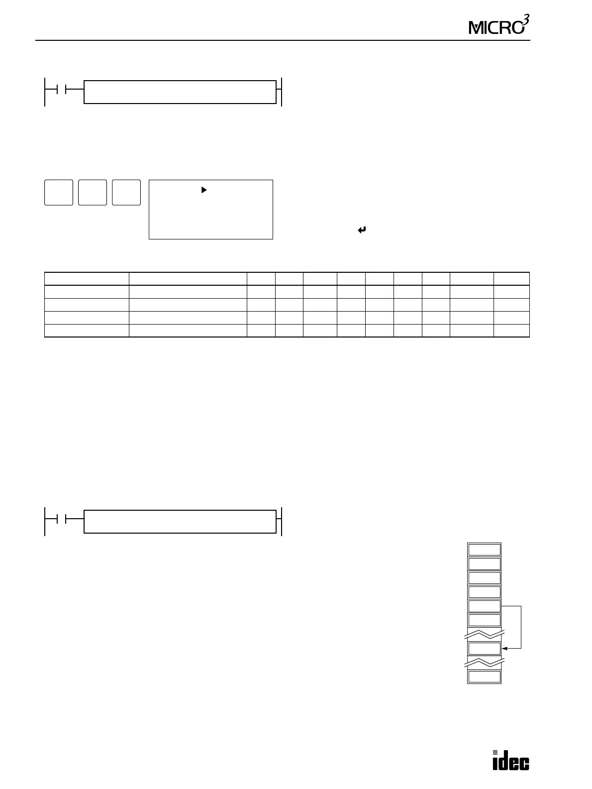
I0
IMOV REP
**
D20 + C10 → D10 + D25
Source operand S1 and destination operand D1 determine the type of operand. Source operand
S2 and destination operand D2 are the offset values to determine the source and destination
operands.
If the current value of counter C10 designated by source operand S2 is 4, the source data is
determined by adding the offset to data register D20 designated by source operand S1:
D(20 + 4) = D24
If data register D25 contains a value of 20, the destination is determined by adding the offset to
data register D10 designated by destination operand D1:
D(10 + 20) = D30
As a result, when input I0 is on, the data in data register D24 is moved to data register D30.
D23
D22
6450
D24
6450
D30
S1
D20
D2
D25
D1
D10
S2
C10
D21
D20
20
D25
4
C10