1: GENERAL INFORMATION
1-18 USER’S MANUAL
Program Loader Specifications
Power Supply
• Supplied by the MICRO
3
base unit through the loader cable.
• Supplied by an AC adapter during off-line programming.
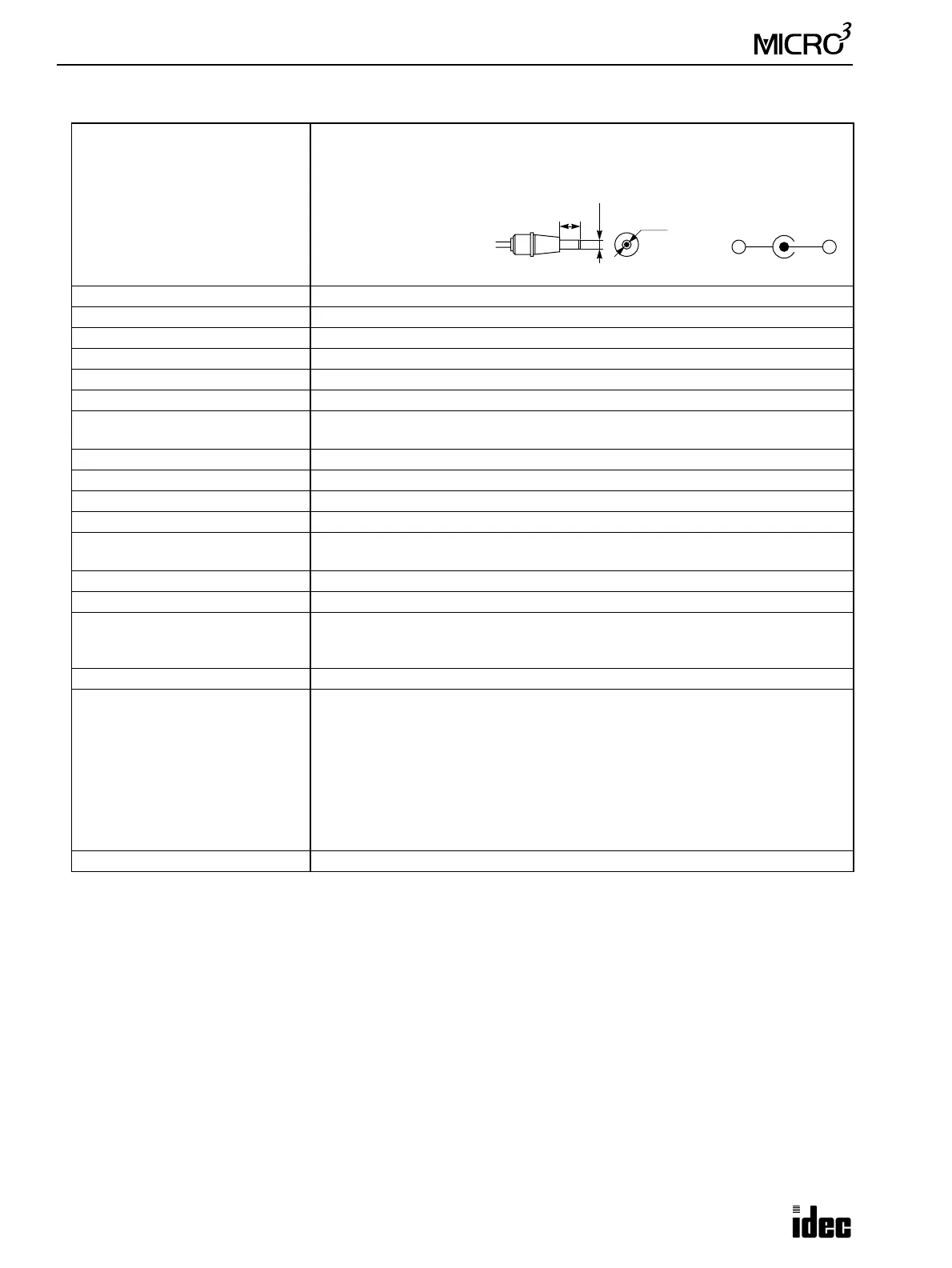
Applicable AC adapter 5 to 6.5 V DC, 4W
Output plug:
Operating Temperature 0 to 50°C
Storage Temperature –20 to +70°C
Relative Humidity Relative humidity severity level RH1, 30 to 95% (non-condensing)
Pollution Degree 3 (IEC 664)
Vibration Resistance 5 to 55 Hz, 60 m/sec
2
, 2 hours each in 3 axes
Shock Resistance 300 m/sec2, 11 msec, 3 shocks each in 3 axes
Power Consumption
Normal operation: Approx. 1.5W
Writing to flash PROM: Approx. 2.5W
Mounting Method The permanent magnet on the back of the program loader attaches to iron panels.
Dimensions 185H × 95W × 30D mm (7.283"H × 3.740"W × 1.181"D)
Weight Approx. 300g
Noise Immunity Withstands the noise same as the MICRO
3
noise immunity
Display
4 lines × 16 characters
Back-lighted LCD with automatic turn off function
Program Key 35 keys, membrane switch key pad (key sheet replaceable)
Control Switch RUN/STOP for MICRO
3
operation
Connection to MICRO
3
Using loader cable FC2A-KL1 (2m/6.56 ft.) or FC2A-KL2 (5m/16.4 ft.), round 8-pin
DIN connector
Baud rate: 9600 bps, using RS485 special protocol
Power Failure Protection Approx. 1 hour at 25°C, using a super capacitor
Memory Card
Compliance with JEIDA Ver. 4.0/PCMCIA Rel. 1.0
Accessible capacity 256K bytes
SRAM card (with battery)
User program storage
Read, write, and battery voltage drop detection
Applicable cards: Fujitsu, Mitsubishi, Rohm, Fuji Electrochemical, Towa Electron
PROM card
Upgrade system program storage (128K bytes)
Read only
User Program Edit Capacity 8K steps maximum
9.5
ø2.1
ø5.5
Polarity
+
–
Dimensions in mm.