17: HIGH-SPEED COUNTER INSTRUCTIONS
USER’S MANUAL 17-5
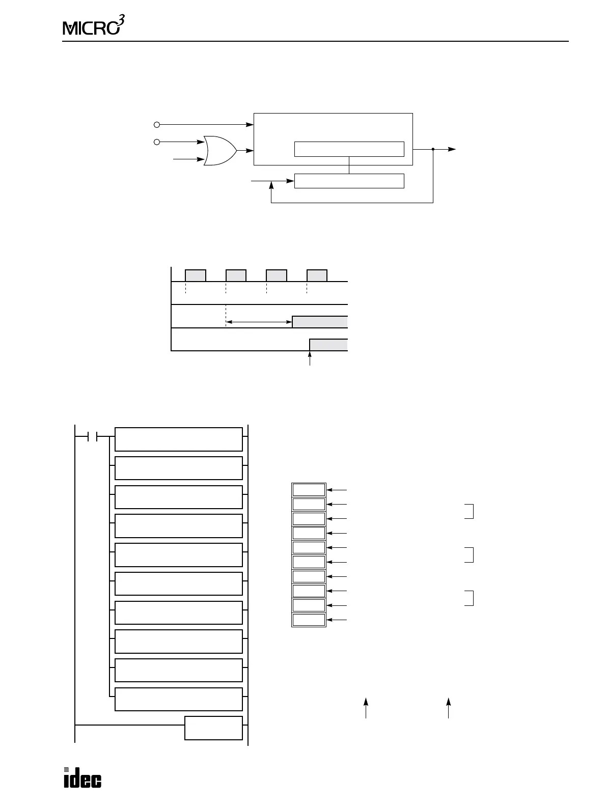
Block Diagram (HSC1: Multi-stage Comparison)
HSC1 counts input pulses to input I0. When the preset value is reached, comparison output is turned on. Multiple preset
values and comparison outputs can be programmed.
Output Delay (HSC1: Multi-stage Comparison)
After the HSC1 has counted the Nth input pulse (the preset value), the output or internal relay designated as destination of
comparison result is turned on with a delay shown below.
Example: HSC1
This example demonstrates a 3-stage high-speed counter operation using the HSC1 instruction.
Pulse Input I0
Hard Reset Input I1
Soft Reset M315
Pulse
Reset
32-bit Comparison Register
32-bit Counter
Comparison Output
Preset Value
When a preset value is reached,
the next preset value is set.
Pulse Input I0
ON
OFF
Comparison Result
ON
OFF
Comparison Result
ON
OFF
N–1
HSC1 Current Value
N N+1 N+2
(Output)
(Internal Relay)
300 µsec maximum
END Executed
Next Scan
When an output is designated as destination oper-
and, the maximum output delay can be 300 µsec,
not including the delay in the hardware.
When an internal relay is designated as destina-
tion operand, the delay can be 1 scan time at the
maximum.
Note: After the last preset value has been reached,
the HSC1 current value continues to increase.
MOV S1
S1
D10
3
M301 is the initialize pulse special internal relay used to execute the MOV
(move) instructions at start up.
The MOV instructions set data to data registers D10 through D19.
M301
REP
**
D1
D10
MOV
S1
0
REP
**
D1
D11
MOV S1
10000
REP
**
D1
D12
MOV
S1
200
REP
**
D1
D13
MOV S1
0
REP
**
D1
D14
MOV S1
50000
REP
**
D1
D15
MOV
S1
201
REP
**
D1
D16
MOV S1
1
REP
**
D1
D17
MOV
S1
34464
REP
**
D1
D18
MOV S1
202
REP
**
D1
D19
200
D13
10000
D12
0
D14
0
D11
3
D10
50000
D15
10,000
50,000
201
D16
1st-stage preset (upper digits)
1st-stage preset (lower digits)
1st-stage output (200 = Output Q0)
2nd-stage preset (upper digits)
2nd-stage preset (lower digits)
2nd-stage output (201 = Output Q1)
Quantity of preset stages
1
D17
34464
D18
100,000
202
D19
3rd-stage preset (upper digits)
3rd-stage preset (lower digits)
3rd-stage output (202 = Output Q2)
Preset value 100,000 is set to two data registers D17 (upper digits) and D18
(lower digits). Values for the two data registers are calculated by dividing
the preset value by 65,536 (10000h) as follows:
100,000 ÷ 65,536 = 1 and remainder 34,464
Upper Digits (D17) Lower Digits (D18)
HSC1
HIGH