17: HIGH-SPEED COUNTER INSTRUCTIONS
17-4 USER’S MANUAL
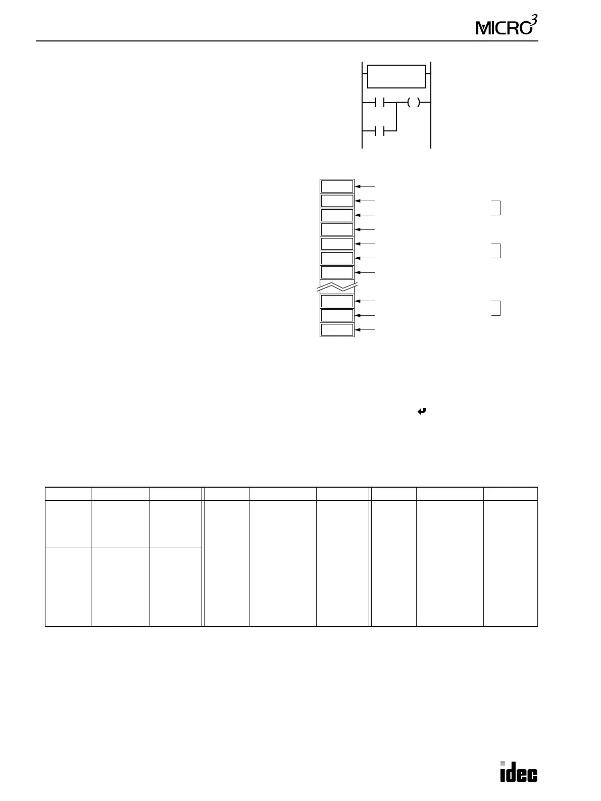
Soft Reset Special Internal Relay M315
In addition to the hard reset using input I1, the high-speed counter current
value can be reset by turning special internal relay M315 on using another
input, output, or internal relay. M315, if used, must be programmed imme-
diately after the HSC1 instruction as shown on the right.
Multi-stage Data Setting
The data of comparison stages, preset values, and
comparison outputs are stored in consecutive data
registers starting with the data register designated by
source operand S1.
Store the quantity of preset stages in the first data
register.
In the next two data registers, store the upper and
lower digits of the preset value for the first stage.
In the fourth data register, store the destination of the
first-stage comparison output, using a numeric allo-
cation number of output or internal relay. See below.
Store data in these data registers before executing the
HSC1 instruction.
Preset Value
The preset value can be 1 through 4,294,967,295 (FFFF FFFFh), which is stored in two consecutive data registers. The
first data register stores the upper digits, and the next data register stores the lower digits. To enter a double-word value to
two consecutive data registers using the program loader, from the editor mode press the MON, D, data register number,
ADV, followed by the LOD/10 (decimal) or OUT/16 (hexadecimal), data register value, and keys. See page 3-16. If the
preset value is changed during high-speed counter operation, the high-speed counter remains unchanged for that cycle.
The change will be reflected in the next count cycle after resetting.
Allocation Numbers: Numeric and Symbolic
Use the numeric allocation numbers to specify the destination of the HSC1 comparison outputs.
Input Filter and Input Frequency
MICRO
3
has hard and soft filter functions. Only the hard filter works on high-speed counter instructions. The hard filter set-
tings affect the input response. See page 4-3. The maximum input frequency for the HSC1 instruction is 5 kHz.
Operand Symbolic Numeric Operand Symbolic Numeric Operand Symbolic Numeric
Output
Q0 - Q7
Q10 - Q11
Q20 - Q27
Q30 - Q31
200 - 207
210 - 211
220 - 227
230 - 231
Internal
Relay
M70 - M77
M80 - M87
M90 - M97
M100 - M107
M110 - M117
M120 - M127
M130 - M137
M140 - M147
M150 - M157
M160 - M167
M170 - M177
470 - 477
480 - 487
490 - 497
500 - 507
510 - 517
520 - 527
530 - 537
540 - 547
550 - 557
560 - 567
570 - 577
Internal
Relay
M180 - M187
M190 - M197
M200 - M207
M210 - M217
M220 - M227
M230 - M237
M240 - M247
M250 - M257
M260 - M267
M270 - M277
M280 - M287
580 - 587
590 - 597
600 - 607
610 - 617
620 - 627
630 - 637
640 - 647
650 - 657
660 - 667
670 - 677
680 - 687
Internal
Relay
M0 - M7
M10 - M17
M20 - M27
M30 - M37
M40 - M47
M50 - M57
M60 - M67
400 - 407
410 - 417
420 - 427
430 - 437
440 - 447
450 - 457
460 - 467
M301 is the initialize
pulse special internal
relay.
HSC1
****
S1
D10
M301
I10
M315
200
D13
34464
D12
3
D14
9
D10+3N–2
1
D11
N
D10
3392
D15
100,000
200,000
201
D16
10176
D10+3N–1
206
D10+3N
When data register D10 is designated as source operand S1
1st-stage preset (upper digits)
1st-stage preset (lower digits)
600,000
1st-stage output (200 = Output Q0)
2nd-stage preset (upper digits)
2nd-stage preset (lower digits)
2nd-stage output (201 = Output Q1)
Nth-stage preset (upper digits)
Nth-stage preset (lower digits)
Nth-stage output (206 = Output Q6)
Quantity of preset stages