16: PULSE, A/D CONVERSION INSTRUCTIONS
16-2 USER’S MANUAL
Example: PULS
This example explains how to set 1-kHz output pulses using the PULS instruction.
From the table on the preceding page, MODE 3 and MODE4 can be used to set 1 kHz. If MODE4 is selected, then
Pulse width coefficient 72 should be used as source operand S1.
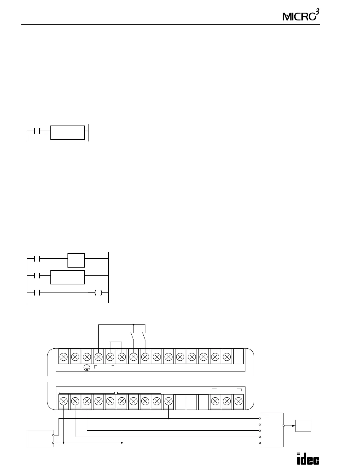
Example: Pulse Motor Speed Control Using PULS Instruction
This example demonstrates a program to control the rotating speed of a pulse motor using the PULS instruction. Analog
potentiometer 0 is used to change the pulse motor speed. When input I0 is on, the pulse output is generated to rotate the
pulse motor. When input I1 is on, the pulse motor rotates in the reverse direction.
Operands
I0 Input to execute the PULS instruction and start the pulse motor
I1 Input to reverse the pulse motor rotation
Q0 Pulse output
Q1 Output to reverse the pulse motor rotation
D10 Pulse width coefficient
MODE1 9.574 through 406.901 Hz
I/O Wiring Diagram
Pulse
Width
Coefficient
S1
Base
Frequency
Output
Frequency 2
×
---------------------------------------------------- 6–=
156250
1000 2
×
---------------------6–=
72.125=
When input I0 is on, output Q0 generates pulse outputs of 1001.6 Hz.
I0
PULS
MODE4
S1
72
Output
Frequency
156250
72 6+
()
2
×
----------------------------- 1001.6
Hz==
M317
PULS
MODE1
S1
D10
I0
ANR0
D10
I1
Q1
M317 is the in-operation output special internal relay which remains on while the
program is executed.
The ANR0 (analog read 0) instruction sets the value of analog potentiometer 0 to
data register D10.
While input I0 is on, the PULS instruction is executed to generate output pulses
determined by the value of D10. Output Q0 sends out the output pulses.
When input I1 is on, output Q1 is turned on to reverse the pulse motor.
OUT
COM0(–)
0123
OUT
COM1(–)
456
DATA LINK
ASGB
+V
+V
CW/CCW
PULSE
GND
Pulse
Motor
+
–
External
Power
24V DC
Motor Driver
100-240V AC
LN
DC OUT
24V 0V
DC IN
COM
0123456710
MICRO
3
Base Unit FC2A-C16B1
(Transistor Sink Output)