17: H
IGH
-
SPEED
C
OUNTER
I
NSTRUCTIONS
17-2 U
SER
’
S
M
ANUAL
Allocation Numbers
The HSC0 instruction uses the following input and internal relay numbers:
Pulse input: Input I0
Hard reset input: Input I1
Soft reset special internal relay: Internal relay M315 (When M315 is on, the current value is reset to 0.)
Hard Reset Selection
Input I1 can be used to reset the current value of high-speed counter HSC0.
LOW:
Resets the current value when input I1 is turned off. HSC0 is enabled while I1 is on.
HIGH: Resets the current value when input I1 is turned on. HSC0 is enabled while I1 is off.
*–––: Disables hard reset. (Input I1 can be used as an ordinary input.)
Soft Reset Special Internal Relay M315
In addition to the hard reset using input I1, the high-speed counter cur-
rent value can be reset by turning special internal relay M315 on using
another input, output, or internal relay. M315, if used, must be pro-
grammed immediately after the HSC0 instruction as shown on the
right.
Preset Value
The preset value can be 1 through 4,294,967,295 (FFFF FFFFh), which is designated using a constant or two consecutive
data registers. The first data register designated by source operand S1 stores the upper digits, and the next data register
stores the lower digits. To enter a double-word value to two consecutive data registers using the program loader, from the
editor mode press the MON, D, data register number, ADV, followed by the LOD/10 (decimal) or OUT/16 (hexadecimal),
data register value, and keys. See page 3-16. If the preset value designated by a data register is changed during high-
speed counter operation, the high-speed counter remains unchanged for that cycle. The change will be reflected in the next
count cycle after resetting.
Input Filter and Input Frequency
MICRO
3
has hard and soft filter functions. Only the hard filter works on high-speed counter instructions. The hard filter set-
tings affect the input response. See page 4-3. The maximum input frequency for the HSC0 instruction is 10 kHz.
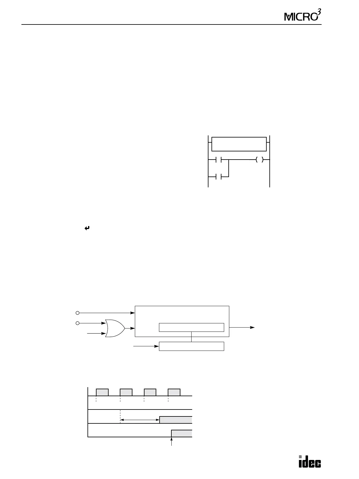
Block Diagram (HSC0: Single-stage Comparison)
HSC0 counts input pulses to input I0. When the preset value is reached, comparison output is turned on.
Output Delay (HSC0: Single-stage Comparison)
After the HSC0 has counted the Nth input pulse (the preset value), the output or internal relay designated by destination
operand D1 is turned on with a delay shown below.
M301 is the initial-
ize pulse special
internal relay.
HSC0
****
S1 D1
M100100
M301
I10
M315
Pulse Input I0
Hard Reset Input I1
Soft Reset M315
Pulse
Reset
32-bit Comparison Register
32-bit Counter
Comparison Output
Preset Value
Pulse Input I0
ON
OFF
Comparison Result
ON
OFF
Comparison Result
ON
OFF
N–1
HSC0 Current Value
N N+1 N+2
(D1 = Output)
(D1 = Internal Relay)
300 µsec maximum
END Executed
Next Scan
When an output is designated as destination oper-
and D1, the maximum output delay can be 300
µsec, not including the delay in the hardware.
When an internal relay is designated as destina-
tion operand D1, the delay can be 1 scan time at
the maximum.
Note: After the preset value has been reached, the
HSC0 current value continues to increase.