18: TROUBLESHOOTING
USER’S MANUAL 18-5
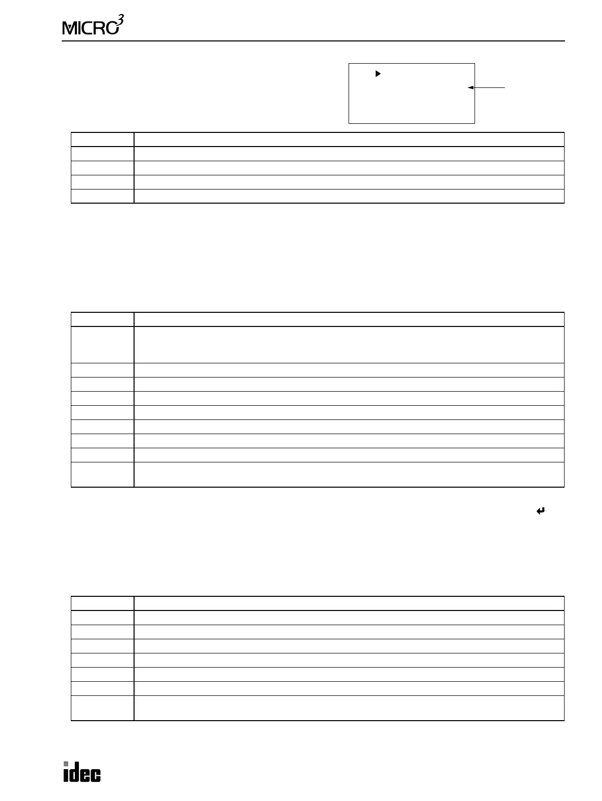
Advanced Instruction Syntax Error (ADV Error)
When a user program syntax error (error code 80h—error
related with advanced instruction) is indicated with type code 5,
6, or 7, the detailed information can be viewed from the error
code indicated in the ADV Error line.
Correct the error in the user program and transfer the corrected user program to MICRO
3
. The error code is cleared when a
correct user program is transferred.
User Program Execution Error (RUN Error)
This error indicates that invalid data is found during execution of a user program. When this error occurs, special internal
relay M304 (user program execution error) is also turned on. The detailed information of this error can be viewed from the
error code indicated in the RUN Error line. This error code is stored in control data register D93, if enabled using FUN10.
See page 5-8. When this error occurs, program operation and all output statuses are maintained.
Remove the cause of the error, and clear the error code using FUN20 on the program loader. Special internal relay M304 is
reset when restarting the MICRO
3
operation; M304 can also be reset using the program loader (MON, M304, RST, ).
Link Communication Error (COM Error)
This error indicates a communication error in the expansion link or data link system. When this error occurs, special inter-
nal relay M305 (link communication error) is also turned on. The detailed information of this error can be viewed from the
error code indicated in the COM Error line. This error code is stored in control data register D94, if enabled using FUN10.
See page 5-8. When this error occurs, program operation and all output statuses are maintained.
When more than one error is detected in the expansion link or data link system, the total of error codes is indicated. For
example, when framing error (error code 2h) and BCC error (error code 10h) are found, error code 12 is displayed.
Error Code Error Details
1 The internal allocation number of the operand is invalid.
2 Input or special internal relay is designated as a destination.
3 Quantity of repeat cycles is set to 32 (or shift bits to 16 for shift/rotate instructions) or more.
4 Advanced instruction which is not allowed for repeat usage is programmed more than once.
Error Code Error Details
1
As a result of an advanced instruction, a value exceeding 9999 is written into the timer/counter preset
value. Data is written into the preset value of a timer/counter which is not included in the user program or
which uses a data register as a preset value.
2 Data register used as a preset value for timer, counter, or counter comparison instruction exceeds 9999.
3 Indirect operand for the IMOV or IMOVN instruction is out of range.
4 Overflow or underflow has resulted from advanced instruction.
5 Division by 0.
6 Invalid data occurred during data conversion for the DISP or DGRD instruction.
7 Attempt was made to write invalid value to calender/clock data.
8 Data register used as an operand for the PULS or PWM instruction contains invalid data.
9
The quantity of multi-stage preset data for high-speed counter HSC1 exceeds available data registers.
Invalid numeric allocation number is designated as a comparison output of the HSC1.
Error Code Error Details
1h Overrun error (Data is received when the receive data registers are full.)
2h Framing error (Failure to detect start or stop bit.)
4h Parity error (An error was found by the parity check.)
8h Receive timeout (Line disconnection)
10h BCC (block check character) error (Disparity with data received up to BCC.)
20h Retry cycle over (Error occurred in all 3 trials of communication.)
40h
I/O definition quantity error (Error in the connection to the FA-3S series PF3S-SIF4 serial interface mod-
ule)
FUN 20 ERROR 80
ADV Error( 4)
RUN Error( 0)
COM Error( 0)
Error Code