18: TROUBLESHOOTING
18-4 USER’S MANUAL
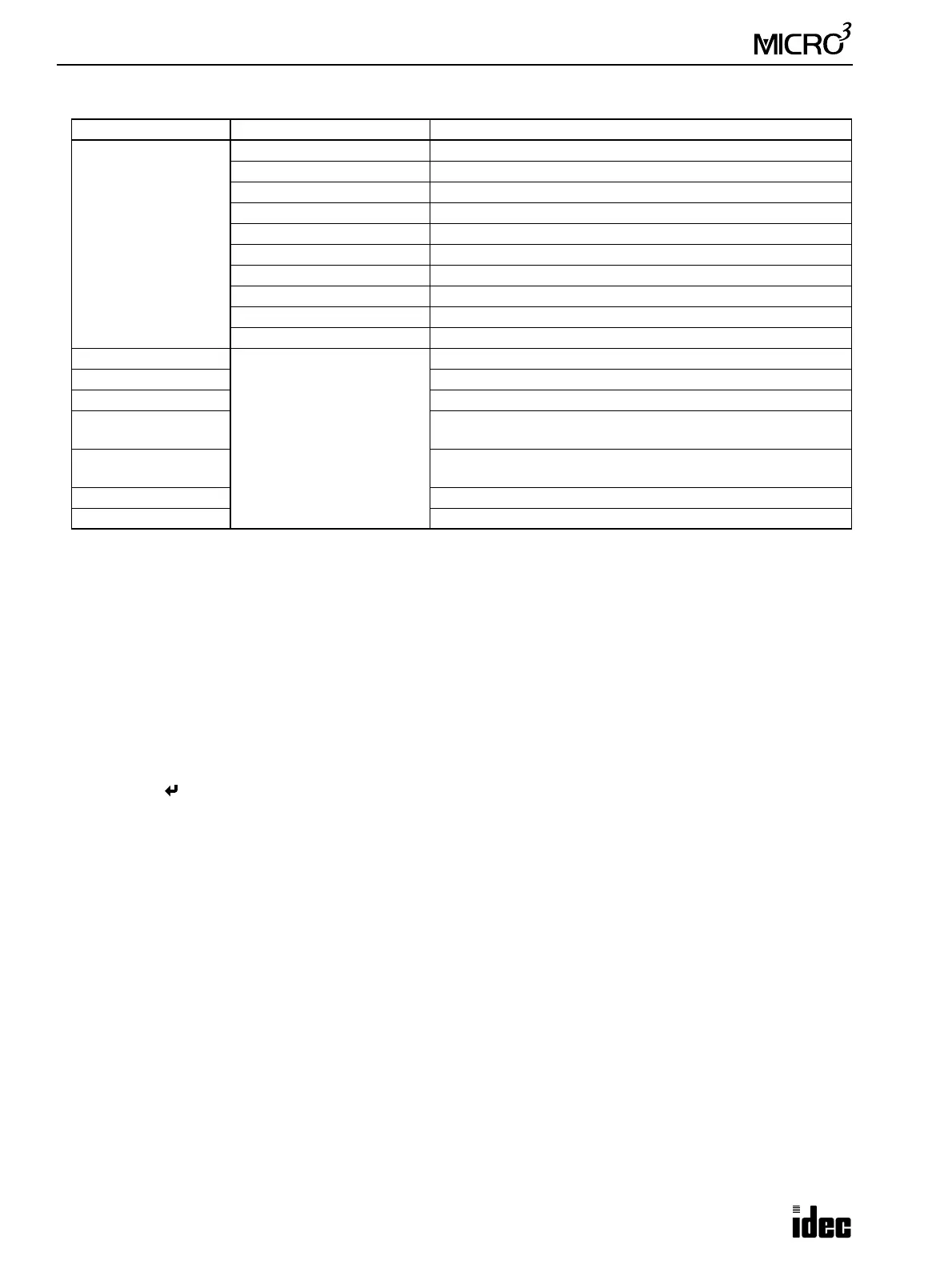
User Program Syntax Error Type Code and Address Code
Note: When type code 5, 6, or 7 is displayed, the details are shown by the error code of the ADV Error (advanced instruc-
tion syntax error). See the next page.
100h: User Program Writing Error (EEPROM NG)
This error indicates a failure of writing into the MICRO
3
base unit EEPROM when transferring a user program or when set-
ting user program protection. The error code is cleared when writing into the EEPROM is completed correctly. If this error
occurs frequently, the MICRO
3
base unit has to be replaced.
200h: Protect Output Overload Error (Transistor NG)
This error is issued when a protect transistor output is overloaded during operation, then only the overloaded output is
forced off. When this error occurs at the base station in the expansion link system, error indicator ERR1 at the base station
is lit. When the error is at the expansion station, error indicator ERR1 is lit at both the base and expansion stations.
If this error has occurred at output Q0 or Q20, then remove the cause of the overload, turn the output off (MON, Q, output
number, RST, ), or turn the output power off. Clear the error code using FUN20 on the program loader.
If this error has occurred at other outputs, then remove the cause of the overload, and the output restores normal operation
automatically. Clear the error code using FUN20 on the program loader.
400h: Sensor Power Overload Error (24V Overload)
This error indicates that the sensor power supply from the MICRO
3
base unit is overloaded. When this error occurs, both
error indicators ERR1 and ERR2 are lit.
When this error occurs at the base station in the expansion link system, error indicators ERR1 and ERR2 are lit at the base
station. When the error is at the expansion station, ERR1 and ERR2 are lit at both the base and expansion stations.
To correct this error, reduce the sensor power output load within the rated value, and either turn power to MICRO
3
off and
on or clear the error code using FUN20 on the program loader.
800h: Calendar/Clock Error (Calendar NG)
This error indicates that the real time calendar/clock in the MICRO
3
base unit has an error caused by invalid clock data due
to voltage drop or by erroneous quartz oscillator operation.
Clear the error code using FUN20, and set the calendar/clock data using FUN28 on the program loader. Turn power off and on
again. If the error continues, the MICRO
3
base unit has to be replaced. See Troubleshooting Diagram 14 on page 18-20.
Type Code Address Code Error Details
1
0001 Stop input number selection error (FUN1)
0002 Reset input number selection error (FUN2)
0003 Internal relay “keep” designation error (FUN3)
0004 Shift register “keep” designation error (FUN4)
0005 Processing mode selection error (FUN5)
0006 Catch input edge selection error (FUN6)
0007 Input filter time selection error (FUN7)
0008 Loader port communication mode setting error (FUN8)
0009 PLC address error for network communication (FUN9)
0010 Control data register setting error (FUN10)
2
0000 to 1012
Address of the incorrect
program
Invalid opcode for basic instruction
3 Invalid operand for basic instruction
4 Invalid timer/counter preset value
5 (Note)
Invalid opcode for advanced instruction
TXD/RXD programmed in the high-speed processing mode
6 (Note)
Invalid data for advanced instruction
Same data register designated as status DR for TXD and RXD
7 (Note) Invalid repeated usage of advanced instruction
8 User program capacity over error