7: BASIC INSTRUCTIONS
USER’S MANUAL 7-19
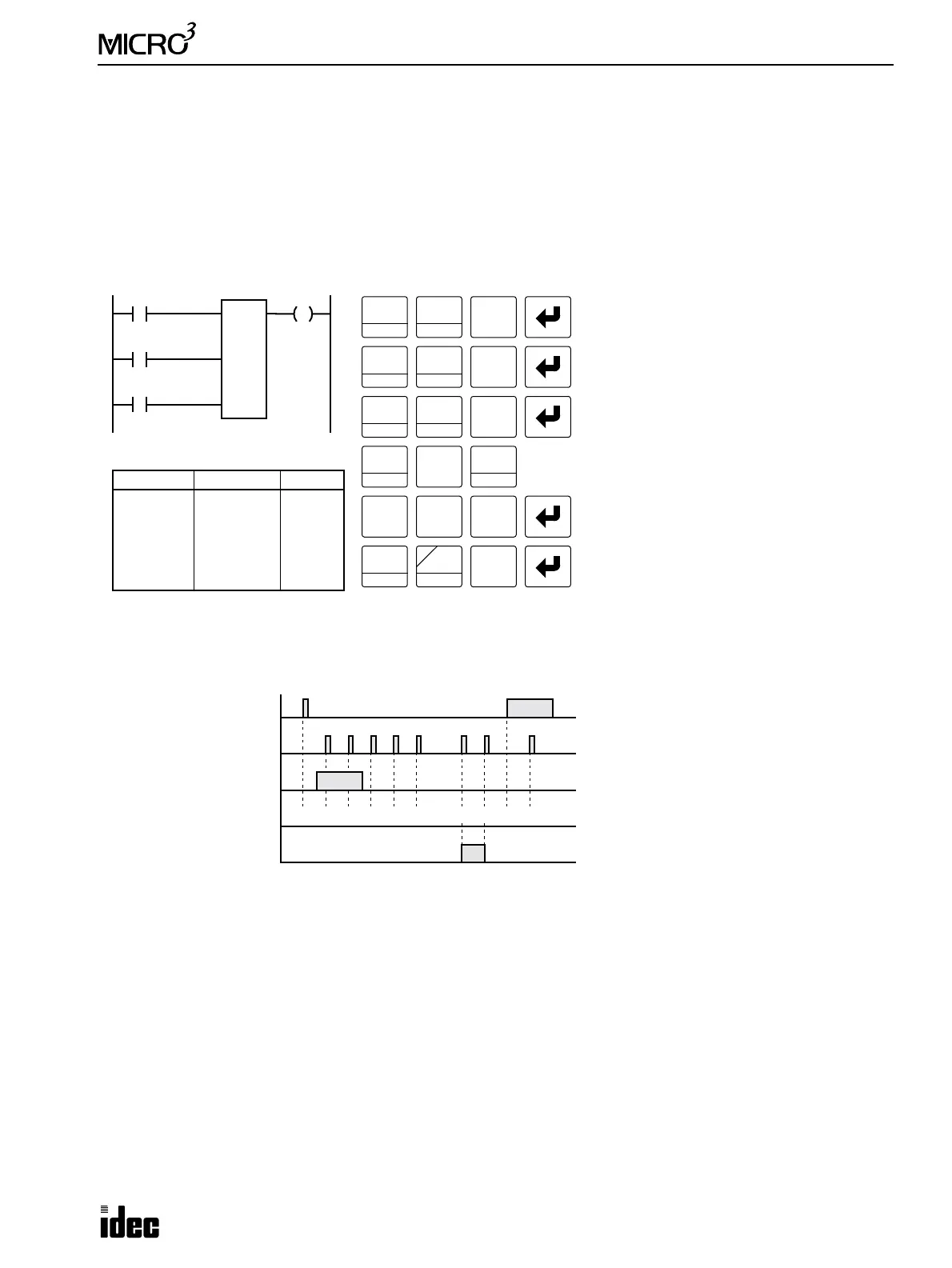
Up/Down Selection Reversible Counter CNT1
The up/down selection reversible counter CNT1 has selection input to switch the up/down gate, so that three inputs are
required. The circuit for an up/down selection reversible counter must be programmed in the following order: preset input,
pulse input, up/down selection input, and the CNT1 instruction, followed by the counter preset value from 0 to 9999.
The preset value can be designated using a decimal constant or a data register. When a data register is used, the data of the
data register becomes the preset value. If the data register designated as a counter preset value holds a value over 9999, a pro-
gram execution error will result, then the error indicator, ERR1, is lit, and the special internal relay, M304, turns on. Data reg-
isters D0 through D99 are available in the standard processing mode and D0 through D31 in the high-speed processing mode.
• The same counter or timer number cannot
be programmed more than once.
• The preset input must be turned on ini-
tially so that the counted value returns to
the preset value.
• The preset input must be turned off before
counting may begin.
• The up mode is selected when the up/
down selection input is on.
• The down mode is selected when the up/
down selection input is off.
• The counter output is on only when the
counted value is zero.
• After the counted value reaches zero
(counting down), it changes to 9999 on the
next count down.
• After the counted value reaches 9999
(counting up), it changes to zero on the
next count up.
• When power is off, the counter’s counted
value is held.
• Counter preset values can be changed
without transferring the entire program to
the MICRO
3
base unit (see page 3-14).
• When the preset value is changed during
counter operation, the change becomes
effective immediately.
Adding (Up) Counters CNT2 through CNT31
Standard counter circuits, using the CNT instruction, feature an adding (UP) counter. There are 30 adding counters CNT2
through CNT31 in the standard processing mode or 14 adding counters CNT2 through CNT15 in the high-speed process-
ing mode.
When counter instructions are programmed, two addresses are required. The circuit for an adding (UP) counter must be
programmed in the following order: reset input, pulse input, the CNT instruction, a counter number 2 through 31, followed
by the counter preset value from 0 to 9999.
The preset value can be designated using a decimal constant or a data register. When a data register is used, the data of the
data register becomes the preset value. If the data register designated as a counter preset value holds a value over 9999, a pro-
gram execution error will result, then error indicator ERR1 is lit, and special internal relay M304 turns on. Data registers D0
through D99 are available in the standard processing mode and D0 through D31 in the high-speed processing mode.
500 500
I1
I0
Ladder Diagram (CNT1)
Key Operation
LOD
10
SET
I
OUT
16
RST
F
Q
Prgm Adrs Instruction Data
0
1
2
3
5
LOD
LOD
LOD
CNT
OUT
I0
I1
I2
1
500
Q0
Program List
LOD
10
C1
500
Q0
1
BPS
0
2
BRD
I2
Preset Input
Pulse Input
Up/Down
LOD
10
SET
I
SET
I
CNT
C
LOD
10
5
CC=
0 0
0
1
BPS
Selection
Preset Input I0
ON
OFF
Pulse Input I1
ON
OFF
U/D Selection Input I2
ON
OFF
Timing Chart
Output Q0
ON
OFF
500 501 502 501
CNT1 Value
500 499 0 9999
• • •
• • •
Note: To enter a decimal con-
stant as a preset value, press the
LOD/10 key followed by the
preset value.