4: SPECIAL FUNCTIONS
USER’S MANUAL 4-17
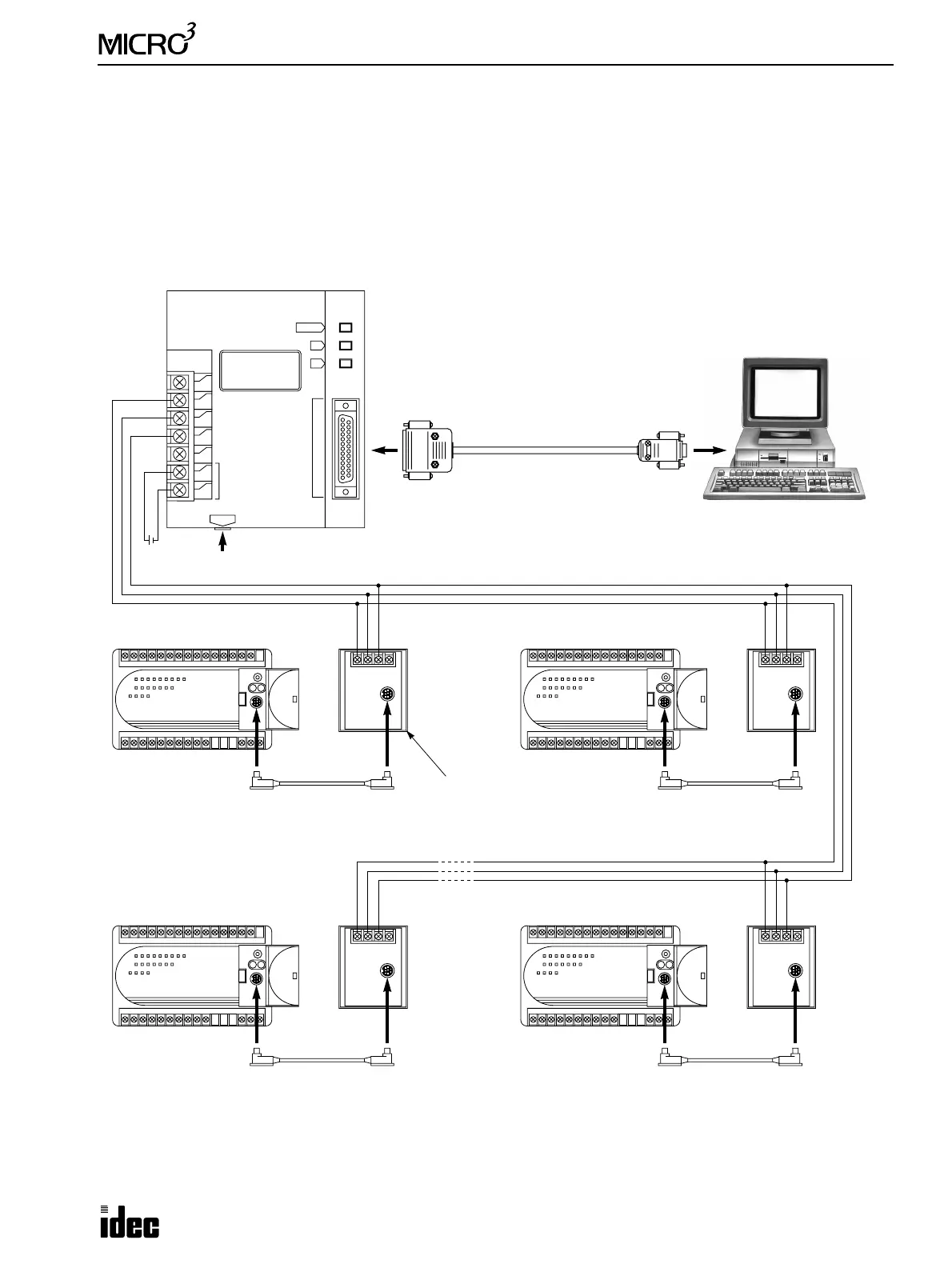
Computer Link 1:N Communication
To set up a 1:N computer link system, connect a computer to RS232C/RS485 converter using RS232C cable HD9Z-C52.
Connect the RS232C/RS485 converter to computer link interface units FC2A-LC1 using shielded twisted pair cables.
Connect MICRO
3
to each computer link interface unit using computer link interface cable FC2A-KC3.
Supply power to the RS232C/RS485 converter by connecting a 24V DC source to terminals 6 and 7 or by plugging an AC
adapter to the DC IN jack. For specifications of the AC adapter, see page A-4.
Use FUN8 Loader Port Communication Mode Setting to make sure that the communication parameters for the MICRO
3
loader port are the same as the computer connected. For FUN8, see page 5-7.
Select a unique PLC address number from 0 through 31 for each MICRO
3
using FUN9 PLC Address for Network Commu-
nication on the program loader and transfer the user program to MICRO
3
. For FUN9, see page 5-7.
RS232C/RS485 Converter FC2A-MD1
132H × 110W × 34D mm
(5.917"H × 4.331"W × 1.339"D)
RS232C Cable
HD9Z-C52
1.5m (4.92 ft.) long
D-sub 9-pin
Female
Connector
To RS232C Port
A B SG FG
To RS232C Port
1st Unit
Computer Link Interface Cable
FC2A-KC3
100 mm (3.937") long
Computer Link Interface Unit
FC2A-LC1
69.5H × 55W × 35.5D mm
(2.736"H × 2.165"W × 1.398"D)
A B SG FG
2nd Unit
A B SG FG
3rd Unit
A B SG FG
Nth Unit (N ≤ 32)
–
+
24V DC or AC Adapter (9V DC, 350 mA)
1
T
2
A
3
B
4
SG
5
FG
6
+
7
–
SD
RD
POWER
DC IN
RS485
SERIAL PORT
POWER SUPPLY
24V DC
RS232C SERIAL PORT
RS232C/RS485
CONVERTER
Type FC2A-MD1
Shielded twisted pair cable 200 meters (656 feet) maximum
Core wire diameter 0.9 mm (0.035") minimum
◆ For the MICRO
3
C, see the MICRO
3
C User’s Manual. ◆