1: GENERAL INFORMATION
1-22 USER’S MANUAL
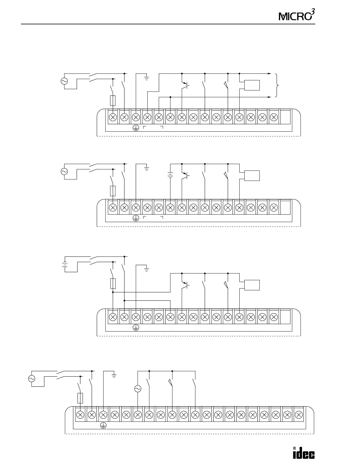
Input Wiring Diagrams, continued
DC Sink Input (AC Power Type)
• When using the sensor power supply from the DC OUT terminals
• When using an external power supply
DC Sink Input (DC Power Type)
AC Input
Sensor
100-240V AC
LN
DC OUT
24V 0V
DC IN
COM
0123456710
100-240V AC
Ground
N
L
Main Power
Switch
Sw
3A Fuse
2-wire
Sensor
–
+
PNP
Transistor
+
–
100-240V AC
Ground
N
L
Main Power
Switch
Sw
3A Fuse
100-240V AC
LN
DC OUT
24V 0V
DC IN
COM
0123456710
External
Power
24V DC
PNP
Transistor
2-wire
Sensor
–
+
24V DC
+–
DC IN
COM
0123456710NC NC
Main Power
Switch
External
Power
24V DC
–
+
3A Fuse
Ground
Sw
2-wire
Sensor
–
+
PNP
Transistor
100-240V AC
LN
AC IN
COM
0123456710NCNCNCNCNCNC NC
Ground
N
L
Main Power
Switch
Sw
3A Fuse
100-120V AC
100-240V AC
Note: The rated voltage of the AC
input is 100 to 120V AC.