4: SPECIAL FUNCTIONS
4-4 USER’S MANUAL
Setting Input Filter
Use FUN7 on the program loader to set the hard filter and soft filter values. See page 5-6.
Hard filter: 0 through 255 (default value is 10)
Input I0 ON pulse = 4 to 616 µsec, Input I0 OFF pulse = 6 to 618 µsec
Inputs I1 to I7 ON pulse = 20 to 625 µsec, Inputs I1 to I7 OFF pulse = 120 to 618 µsec
Soft filter: 0, 3, 7, or 10 msec (default value is 3 msec)
Filtering Operation
Depending on the selected values, the hard and soft filters have three response areas to receive or ignore input signals.
Input reject area: Input signals are ignored and not received definitely.
Input indefinite area: Input signals may be received or ignored.
Input accept area: Input signals are received definitely.
Hard Filter
Three input response areas are calculated for preset value N from the following formula. Use these values for reference only.
Input response areas vary with input signals and hard filter preset values as listed below
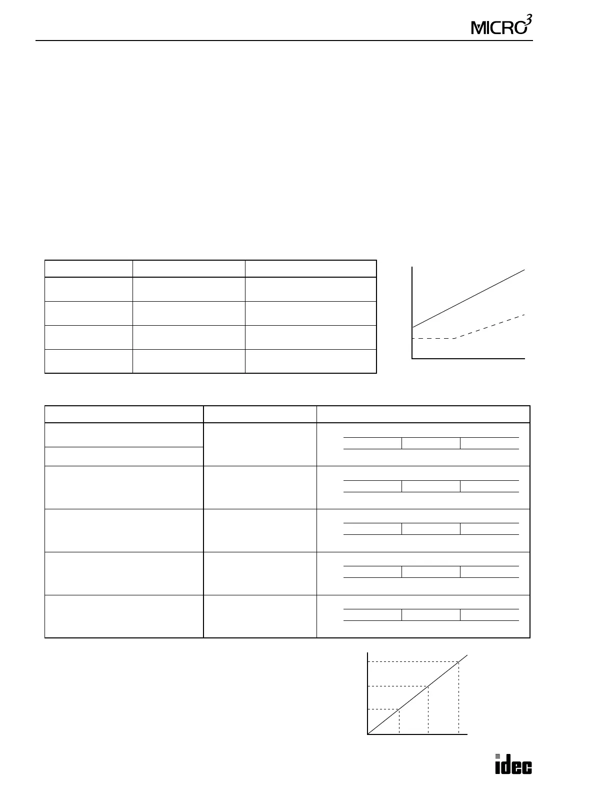
If the hard filter is set to a value smaller than required, MICRO
3
becomes susceptible to noises and malfunctions may occur fre-
quently. As the hard filter is set to a larger value, the maximum
operating frequency of high-speed counters will decrease. The
relationship between the hard filter setting and maximum operat-
ing frequency is shown on the right. When high-speed response is
required in an environment where noise exists, use shielded wires
for input signal lines.
Input Signal Input Accept Area α Input Reject Area β
I0 ON Pulse α > 2.4N + 4 (Equation A)
N ≤ 1: β < 1
N > 1:
β < 0.8N – 1 (Equation B)
I1 to I7 ON Pulse
N ≤ 2:
α > 20
N > 2:
α > 2.4N + 13
N ≤ 138:
β < 8
N > 138:
β < 0.8N – 103
I0 OFF Pulse
α > 2.4N + 6
N ≤ 2:
β < 1
N > 2:
β < 0.8N – 1
I1 to I7 OFF Pulse
N ≤ 47:
α > 120
N > 47:
α > 2.4N + 6
β < 0.8N + 40
Input Signal Example Hard Filter Preset Input Reject, Accept, or Indefinite Area
High-speed counter 10 kHz
A/D conversion
10
Catch input 40-µsec ON pulse
Catch input 110-µsec ON pulse 40
Catch input 260-µsec ON pulse 100
Catch input 500-µsec ON pulse 200
Catch input 200-µsec OFF pulse 80
Pulse
Input Accept Area
Input
Indefinite
Area
Input Reject Area
α
β
Preset Value N
Width
(µsec)
Indefinite
7 µsec 28 µsec
Reject Accept
8 µsec 37 µsec
I0
I1 to I7
Indefinite
31 µsec 100 µsec
Reject Accept
8 µsec 109 µsec
I0
I1 to I7
8 µsec 253 µsec
I1 to I7
Indefinite
79 µsec 244 µsec
Reject Accept
I0
Indefinite
159 µsec 484 µsec
Reject Accept
57 µsec 493 µsec
I0
I1 to I7
Indefinite
63 µsec 198 µsec
Reject Accept
104 µsec 198 µsec
I0
I1 to I7
750 Hz
2 kHz
10 kHz
0 255
Maximum Frequency
Preset Value N10 100
Maximum
Frequency
≅ 200/N kHz
(N ≥ 5)