7: BASIC INSTRUCTIONS
7-8 USER’S MANUAL
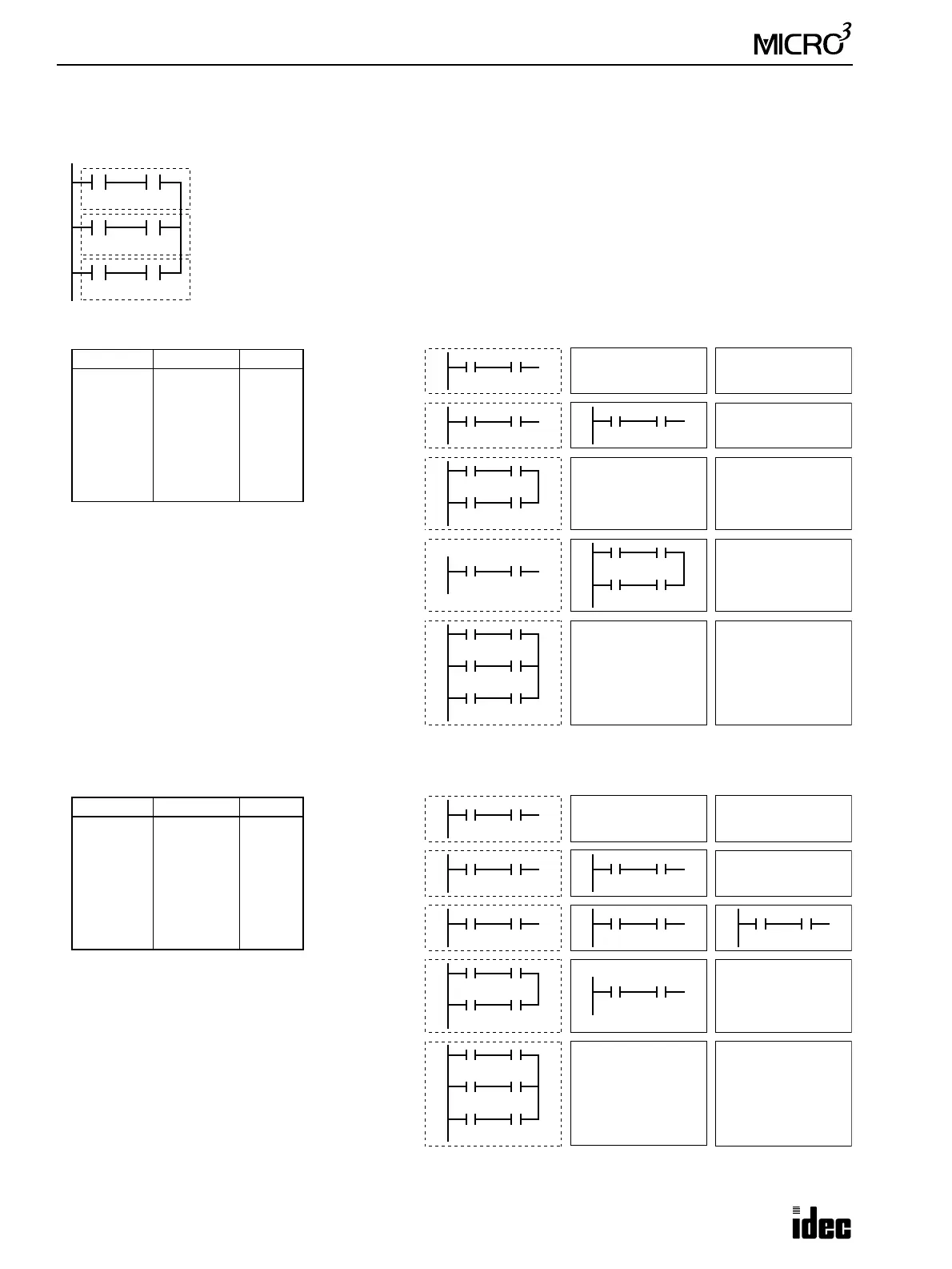
Example: OR LOD (Load)
For the following circuit, the OR LOD instruction can be used in two ways.
First, the OR LOD instruction can be keyed following each of the sets of circuits that
are to be connected in parallel.
Second, the OR LOD instruction can be entered twice at the end, after all the circuits
to be connected in parallel have been keyed.
In either way, there is a relationship between the quantity of LOD instructions and the
quantity of OR LOD instructions:
Quantity of OR LOD instructions = Quantity of LOD instructions – 1
Block A
Ladder Diagram
I1
I2
I3
I4
I5
I6
Block B
Block C
I1
Operation Register Stack Register
LOD I1
AND I2
Prgm Adrs Instruction Data
0
1
2
3
4
5
6
7
LOD
AND
LOD
AND
OR LOD
LOD
AND
OR LOD
I1
I2
I3
I4
I5
I6
Program List 1
I2
I1
I3
I2
I4
LOD I3
AND I4
OR
LOD
LOD I5
AND I6
OR
LOD
The program represented by Block A is
stored beginning with the LOD I1 instruc-
tion, and Block B is stored with LOD I3.
Then, these two programs are read by the
OR LOD instruction which is entered next,
forming a circuit connected in parallel.
The program represented by Block C is stored
beginning with the LOD I5 instruction. This is
read by the final OR LOD instruction, so that it
is connected in parallel with the two programs
connected previously.
I3 I4
I1 I2
I5 I6
I1
I3
I2
I4
I1
I3
I2
I4
I5 I6
I1
Operation Register Stack Register
LOD I1
AND I2
Prgm Adrs Instruction Data
0
1
2
3
4
5
6
7
LOD
AND
LOD
AND
LOD
AND
OR LOD
OR LOD
I1
I2
I3
I4
I5
I6
Program List 2
I2
LOD I3
AND I4
OR
LOD
LOD I5
AND I6
OR
LOD
The program represented by Block A is
stored beginning with the LOD I1 instruc-
tion, Block B is stored with LOD I3, and
Block C is stored with LOD I5.
Then, the OR LOD instruction is entered
twice consecutively, connecting the blocks
in parallel, sequentially.
In this case, the number of stored circuits
and read operations are increased.
I3 I4
I1 I2
I1
I3
I2
I4
I5 I6
I3
I5
I4
I6
I5 I6 I3 I4 I1 I2
I1 I2