7: BASIC INSTRUCTIONS
7-10 USER’S MANUAL
BPS (Bit Push), BRD (Bit Read), and BPP (Bit Pop), continued
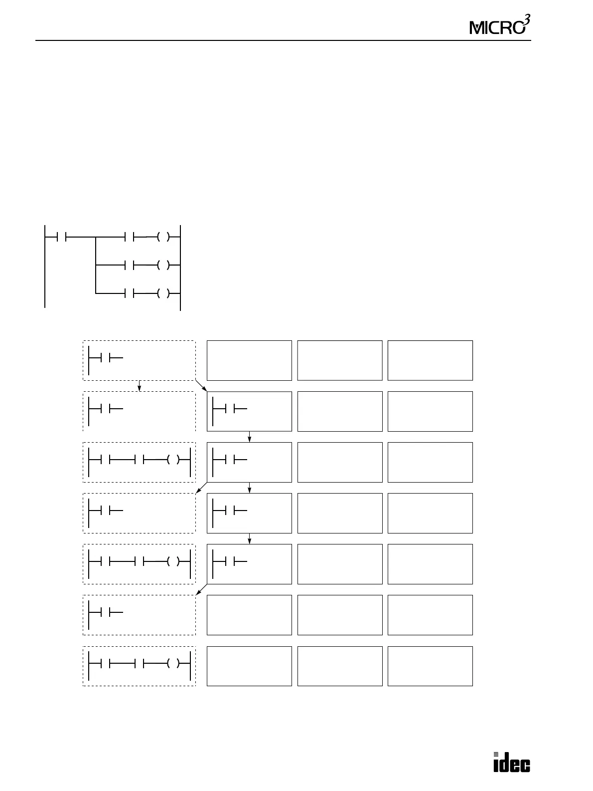
Data Movement in Operation Register and Bit Stack Register
When the BPS (bit push) instruction is used, the program in the operation register is stored in the first bit stack register.
When the BPS instruction is used again, the program in the first stack register is stored in the second bit stack register and
the program in the operation register is stored in the first stack register. Each time the BPS instruction is used, the program
is moved to the next bit stack register. Program blocks can be stored in a maximum of eight bit stack registers.
When the BRD (bit read) instruction is used, the program in the first bit stack register is read to the operation register. All
program blocks stored in bit stack registers are not moved.
When the BPP (bit push) instruction is used, all program blocks in bit stack registers are shifted back by one place. The
program in the first bit stack register is moved to the operation register.
Operation Register Bit Stack Register (8 maximum)
LOD I0
I0
BPS
I0 I0
AND I1
I0
I1 Q1
I0
BRD
I0 I0
I0
I2 Q2
I0
BPP
I0
I0
I3 Q3
OUT Q1
AND I2
OUT Q2
AND I3
OUT Q3
I0
I1
I2
Ladder Diagram
Q1
I3
Q2
Q3
BPS
BPP
BRD