4: S
PECIAL
F
UNCTIONS
4-26 U
SER
’
S
M
ANUAL
Example: A/D Conversion
The following example demonstrates a program to perform ON/OFF control on a heater using the A/D converter unit (4 to
20 mA). The temperature sensor generates an analog output of 4 through 20 mA while the temperature changes from 0°C
through 100°C. The output from the temperature sensor is connected to the A/D converter unit. The output from the A/D
converter unit is connected to input I0 of
MICRO
3
. When the temperature is 50°C or less, output Q0 is turned on to turn the
heater on. When the temperature is above 50°C, output Q0 is turned off to turn the heater off. The temperature is also dis-
played on digital display units.
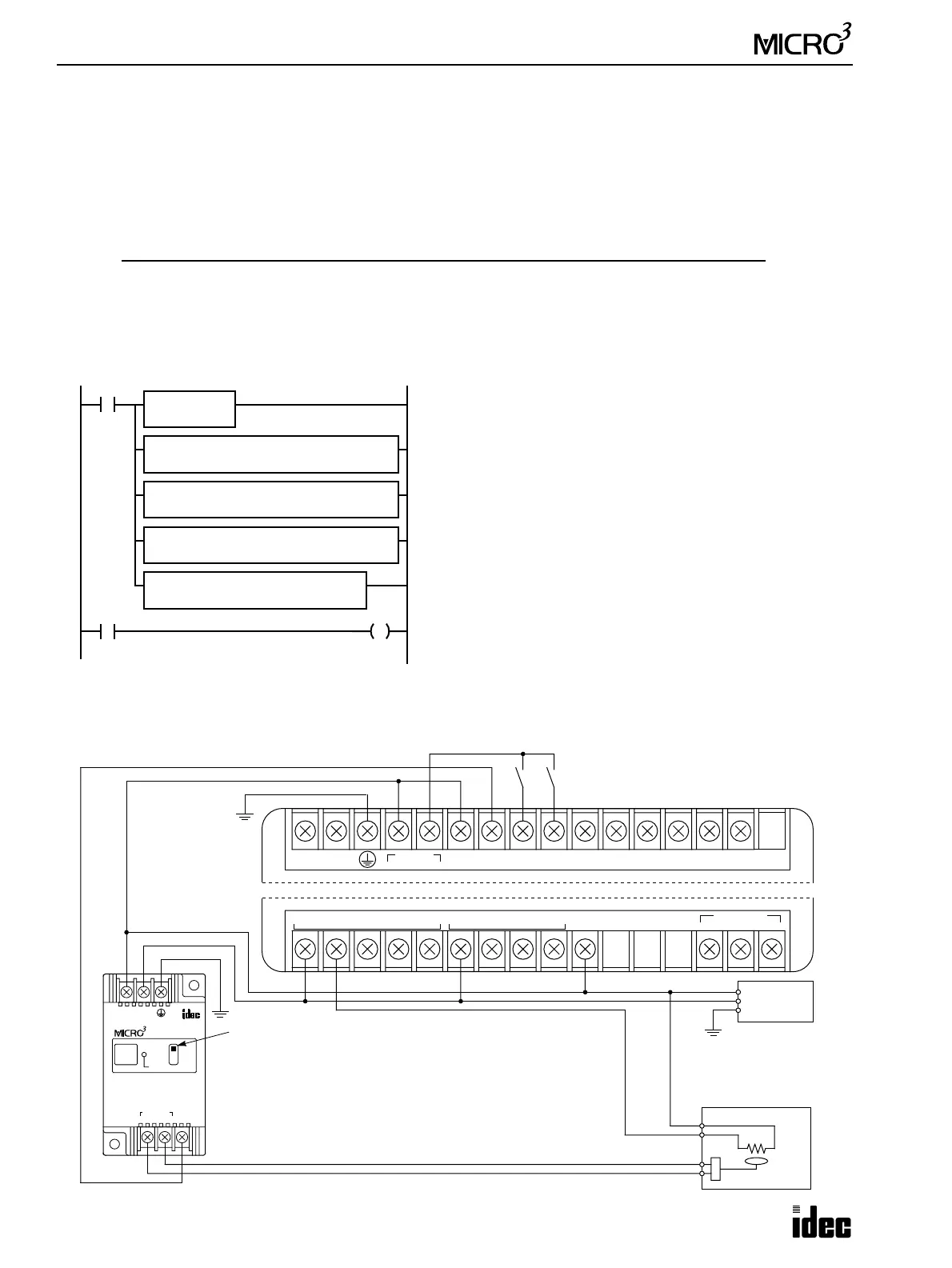
Ladder Diagram
I/O Wiring Diagram
This wiring example shows a source-input, sink-output connection for the
MICRO
3
base unit. Digital display units are con-
nected to outputs Q20 through Q27 at the expansion station (not shown).
Temperature (°C) Sensor Output (mA) A/D Converted Value Heater
04 0ON
50 12 124 ON
51 12.064 125 OFF
100 20 249 OFF
A/D
M317
D1
Q0
M317 is the in-operation output special internal relay.
The analog data from the A/D converter unit is 8-bit converted to a
digital value 0 through 249 and set to data register D0.
When the D0 value is less than or equal to 124, internal relay
M100 is turned on.
The D0 value is multiplied by 10, and the result is set to data reg-
ister D10.
The D10 value is divided by 25, and the result is set to data regis-
ter D11.
The 4-digit D11 value is displayed on display units connected to
outputs Q20 through Q27.
When M100 is on, output Q0 is turned on.
M100
CMP<= S1
D0
S2
124
D1
M100
REP
**
MUL S1
D0
S2
10
D1
D10
REP
**
DIV S1
D10
S2
25
D1
D11
REP
**
08 D0
DISP DAT
BCD4
LAT
LL
S1
D11
Q
Q20
OUT
COM0(–)
0123
OUT
COM1(–)
456
DATA LINK
ASGB
+V
100-240V AC
LN
DC OUT
24V 0V
DC IN
COM
0123456710
MICRO
3
Base Unit FC2A-C16B1
+–
24V DC
A/D UNIT
INPUT
4-20mA
POWER
SINK
SCE
+–
ANALOG WIRE TO
IN 0
INPUT OUTPUT
24V DC
Power
+
–
FG
Heater
4 to 20mA Output from Temperature Sensor
Set the output selector
switch to SINK.
Source Input/Sink Output