Server System Features
Intel
®
Server Board S2600CP Intel
®
Server System P4000CP Family Service Guide 7
Callout Description Callout Description
I Slot 6, PCI Express* Gen3, support riser card AK HDD activity LED
J DIMM E1/E2/F1/F2 AL Main Power
K System Status LED AM SATA 3G connector
L ID LED AN SATA 6G connector
M Diagnostic LED AO SATA SGPIO
N NIC 3/4 (only on Quad NIC board) AP SATA/SAS connector
O USB 0/1/2/3, NIC 1,2 AQ SAS SGPIO 2
P VGA AR Password Clear
Q Serial Port A AS SAS SGPIO 1
R Processor 2 Fan connector AT IPMB
S Processor 2 Power connector AU ME Force Update
T System Fan 7 connector AV BMC Force Update
U DIMM H1/H2/G1/G2 AW HSBP_I2C
V Processor 1 Power connector AX USB to front panel
W DIMM A1/A2/B1/B2 AY BIOS Default
X System Fan 5 connector AZ Intel C600 RAID Upgrade key connector
Y System Fan 6 connector BA BIOS Recovery
Z Processor 1 Fan connector BB Serial B connector
AA DIMM C1/C2/D1/D2 BC
SSI Front Panel (24-pin) and NIC 3/4
LED (4-pin)
AB System Fan 3 connector BD Chassis Intrusion
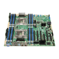
Figure 8. Server Board Connector and Component Locations
Intel
®
Light-Guided Diagnostics
The figure in below shows the locations of Diagnostic LEDs on Intel
®
Server Board S2600CP.
 Loading...
