DISASSEMBLY (See Figure 12D-6)
1. Remove blade and adapter.
2. Remove square drive key.
3. Remove shaft protector.
4. Remove large lock ring.
5. Install blade with adapter.
6. Pull spindle shaft and guide from housing.
NOTE
A suction will be felt when pulling the guide from
the housing. The suction will be broken when
O-ring clears the housing.
7. Remove blade with adapter.
8. Remove small lock ring.
9. Remove spacer, seal and spindle shaft.
NOTE
Perform Step 10 only if spindle housing bearing
is to be changed.
10. Remove motor assembly from spindle housing.
Do not disassemble motor.
11. Remove spindle shaft bearing.
REASSEMBLY (See Figure 12D-6)
1. Install spindle bearing if removed.
2. Install motor onto spindle housing. Torque bolts to
18 ft-lbs. (24 N.m).
3. Install spindle shaft.
4. Install spindle shaft guide.
5. Install large snap ring.
6. Install seat (lip to the inside), spacer and small
lock ring.
7. Install shaft protector and square drive key.
8. Install blade with adapter. Torque center blade
screw to 75 ft-lbs. (102 N.m).
9. Check torque of blade mounting screws, torque to
35–40 ft-lbs. (47–54 N.m).
ATTACHMENTS
SECTION 12D. MOWERS
12D-6
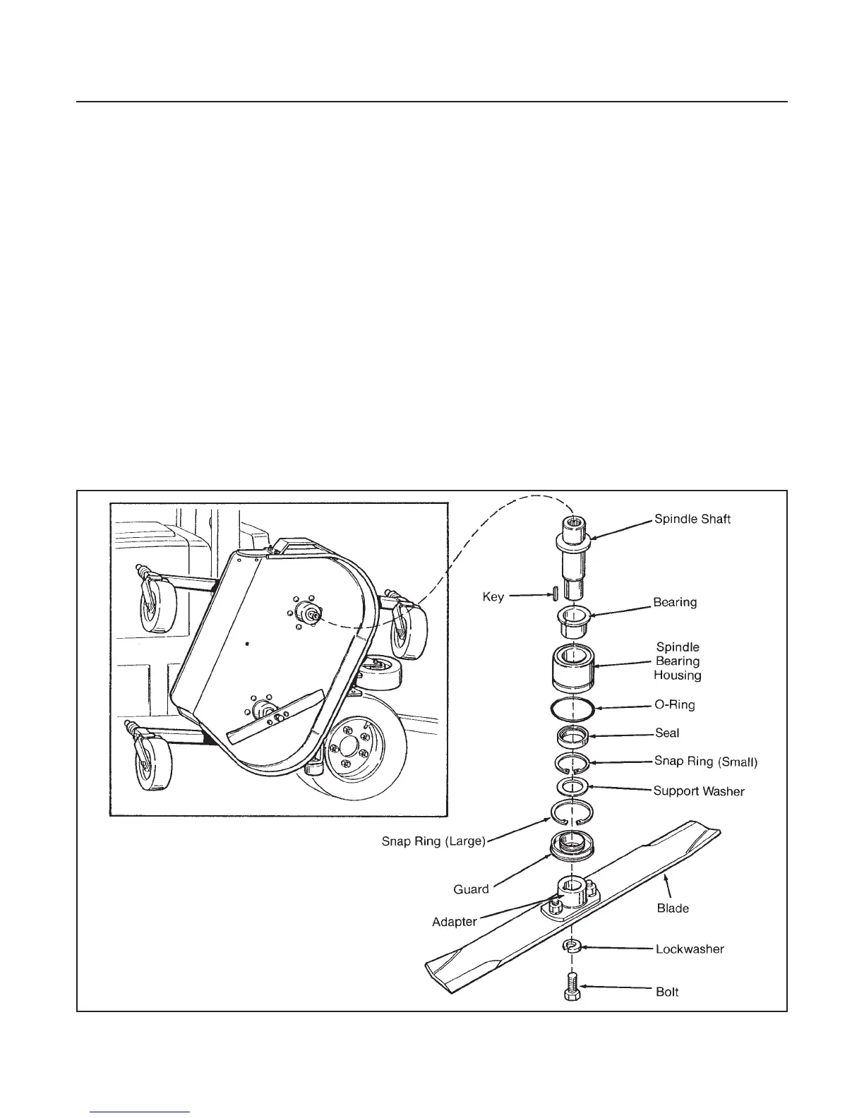
Figure 12D-6. Spindle Assembly
 Loading...


