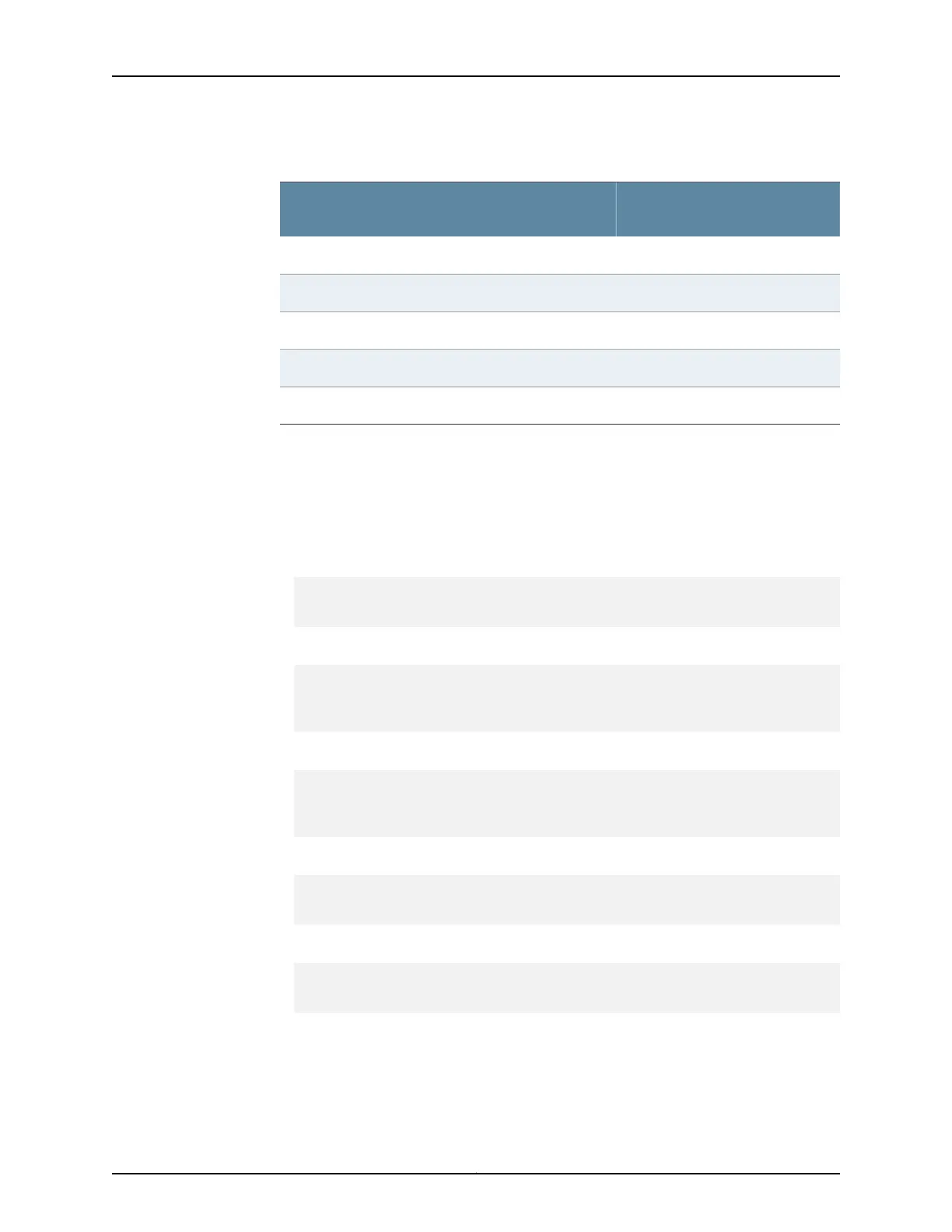
Table 46: M7i Component Power Requirements
Power Requirement (Amps)@ 48
VComponent
0.6 ABase system (cooling system, power supplies, and FIC)
1.4 ACFEB/CFEB-E
1.9 ACFEB/CFEB-E with Adaptive Services Module
1.9 ACFEB-E with MultiServices Module
0.7 ARouting Engine
You can use the information in Table 46 on page 80 and the M7i Multiservice Edge Router
Interface Module Reference to calculate power consumption for various hardware
configurations, input current from a different source voltage, and thermal output, as
shown in the following examples. (For an added safety margin, the examples use a
generalized value for PICs of 0.625 A @ 48 V each.)
•
Power consumption for minimum configuration:
Base system + 1 CFEB + 1 RE + 1 PIC =
0.6 A + 1.4 A + 0.7 A + 0.625 A = 3.3 A @ 48 V = 159 W DC
•
Power consumption for maximum configuration:
Base system + 1 CFEB with ASM + 1 RE + 4 PICs =
0.6 A + 1.9 A + 0.7 A + 4(0.625 A) =
0.6 A + 1.9 A + 0.7 A + 2.5 A = 5.7 A @ 48 V = 274 W DC
•
Input current from a DC source other than –48 VDC (based on maximum configuration):
(–54 VDC input) x (input current X) = (–48 VDC) x (input current Y)
54 x X = 48 x 48.2
X = 48 x 48.2/54 = 42.8 A
•
System thermal output for maximally configured AC-powered router:
Watts DC/85% AC PEM efficiency/0.293 = BTU/hr
274/0.85/0.293 = 1100 BTU/hr
•
System thermal output for maximally configured DC-powered router:
Watts DC/0.293 = BTU/hr
274/0.293 = 935 BTU/hr
Copyright © 2019, Juniper Networks, Inc.80
M7i Multiservice Edge Router Hardware Guide